5-11
SPEEDOMETER
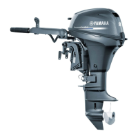
SPEEDOMETER TUBE ROUTING
1. Cut off about 3 mm (0.12 in.) from the end
of the nipple of the speedometer tube to
open it.
2. Route the speedometer tube carefully to
avoid crimping or damage.
3. Connect the tube to the nipple.
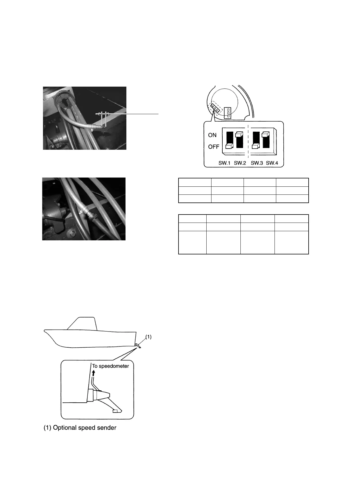
* The optional speed sender (P/N: 688-83556-
01) is required if the speedometer tube is not
equipped to the clamp bracket area.
* In high-performance applications where the
engine has been mounted in an elevated
position, it may be necessary to use the
optional speed sender to obtain a correct
reading.
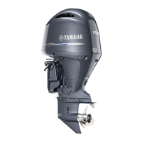
DIGITAL SPEEDOMETER SET UP
1. Remove the rubber grommet from the back
the meter.
2. Set the toggle dipswitches on the chart as
below.
3. Reinstall the grommet.
* The switch position in the illustration shows the
initial setting, which is the mph display and ABYC
fuel sender.
Cut off 3 mm
(0.12 in.)
SW.1 ON OFF OFF
SW.2 ON ON OFF
Display km/h mph knot/h
SW.3 ON OFF OFF
SW.4 ON ON OFF
Fuel
sender
Yamaha
original
5 – 105 Ω
ABYC
(US)
30 – 240 Ω
Europe
180 – 0 Ω
 Loading...