5-15
FUEL MANAGEMENT GAUGE
WIRING DESCRIPTION
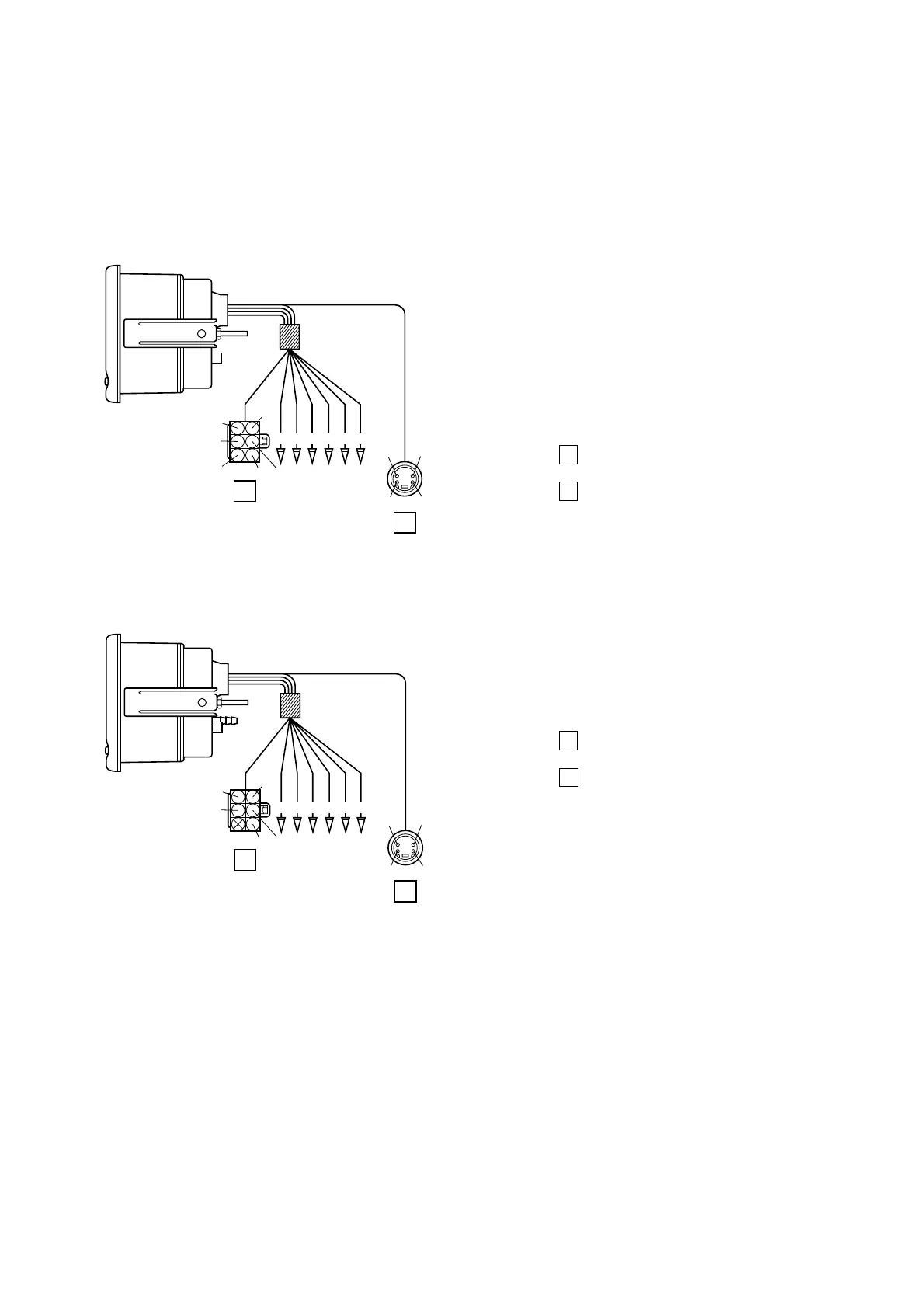
Fuel management gauge
Be sure that both the fuel management gauge and speedometer yellow wires are connected to the
same power source and activated at the same time.
Fuel mgt gauge with speedometer
The speed data is automatically picked up, therefore wiring to the speedometer is not needed.
R: 12 volt
G: To the green wire from “STBD” digital tachom-
eter
G/W: To the green wire from “PORT” digital ta-
chometer for twin motor installations
B: To the ground
L: To the blue wire from digital speedometer
Y: To digital speedometer to the same power
source
Coupler A : To the extension wire lead for the
fuel flow sender
Coupler B : To the digital speedometer or a
NMEA 0183 compatible GPS unit
Pu
Or
Or
Pu/W
W/R
B
R
A
B
Y B L G
G/W
X
R
W
B
R: 12 volt
W: To fuel level sender (Fuel tank)
B: To the ground
L: To light switch
Y: To power source
Coupler A : To the extension wire lead for the
fuel flow sender
Coupler C : To a NMEA 0183 compatible GPS
unit
Pu
Or
Or
Pu/WB
R
A
C
Y B L W
B
X
X
W
X
 Loading...