5-21
COOLANT TEMP. METER
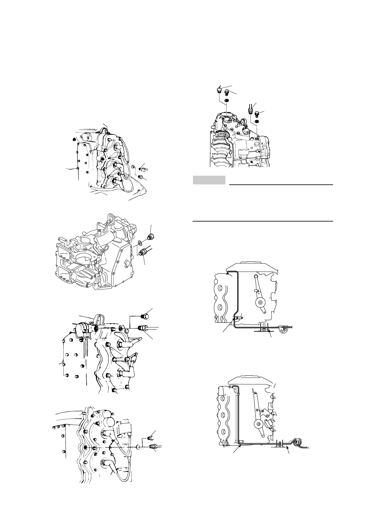
COOLANT PRESS. SENDER AND/OR COOLANT TEMP. SENDER INSTALLATION
(FOR 2-STROKE MODELS)
Remove the screw plug (1) from the cylinder
head and install the sender (2) with gasket.
After installing the sender, check for water
leakage.
[Sender (2): 20 Nm, 2.0 kgf•m, 15 ft•lb]
40V, 50H (50)
E48C, 55B
60F, 70B (70)
75C, 90A (90), 75A, 85A
V4, V6
NOTICE
Install the coolant pressure sender on the
port side. If it is installed on the starboard
side, the sender tube could cause a dam-
age by hard bending.
ROUTING COOLANT TEMP. LEAD
V4
V6 (2.6)
(1)
(2)
(1)
(2)
(1)
(2)
(1)
(2)
(1)
(1)
(2) Coolant temp. sender
(2) Coolant press. sender
Through the
stopper base
Secure with
10-pin harness holder
Through the
stopper base
Secure with
10-pin harness
holder
 Loading...