15
Components
EMU2579Z
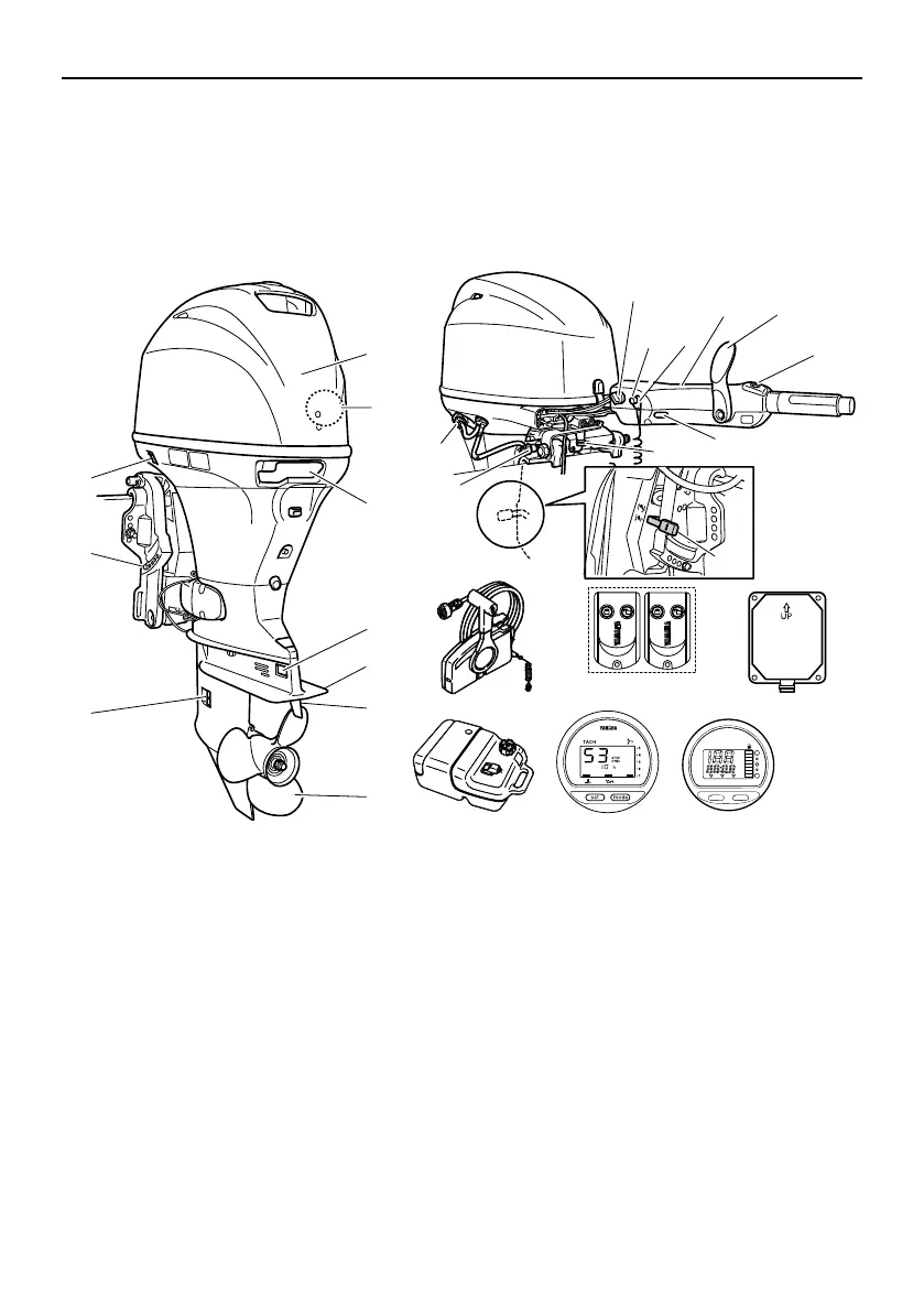
Components diagram
* May not be exactly as shown; also may not be included as standard equipment on all mod-
els (order from dealer).
12
13
15
14
16
19
20
18
1
3
4
6
7
10
9
8
5
2
11
17
ZMU07223
21
25
24
TRIP TIME BATT
Km/h
knot
mph
km
mile
SPEED
YAMAHA
set
mode
23
22
26
27
1. Top cowling
2. Water separator
3. Cowling lock lever
4. Anode
5. Anti-cavitation plate
6. Trim tab (anode)
7. Propeller*
8. Cooling water inlet
9. Clamp bracket
10. Power trim and tilt switch*
11. Variable trolling RPM switch*
12. Gear shift lever*
13. Tiller handle*
14. Clip*
15. Engine stop button/Engine shut-off switch*
16. Main switch*
17. Alert indicator*
18. Steering friction adjuster*
19. Tilt lock lever*
20. Tilt support knob
21. Flushing device
22. Remote control box (side mount type)*
23. Remote control transmitter
24. Receiver
25. Fuel tank
26. Digital tachometer*
27. Digital speedometer*
6BG-9-78-1E0.book 15 ページ 2014年11月20日 木曜日 午後3時3分

 Loading...


