HANDLEBAR
4-34
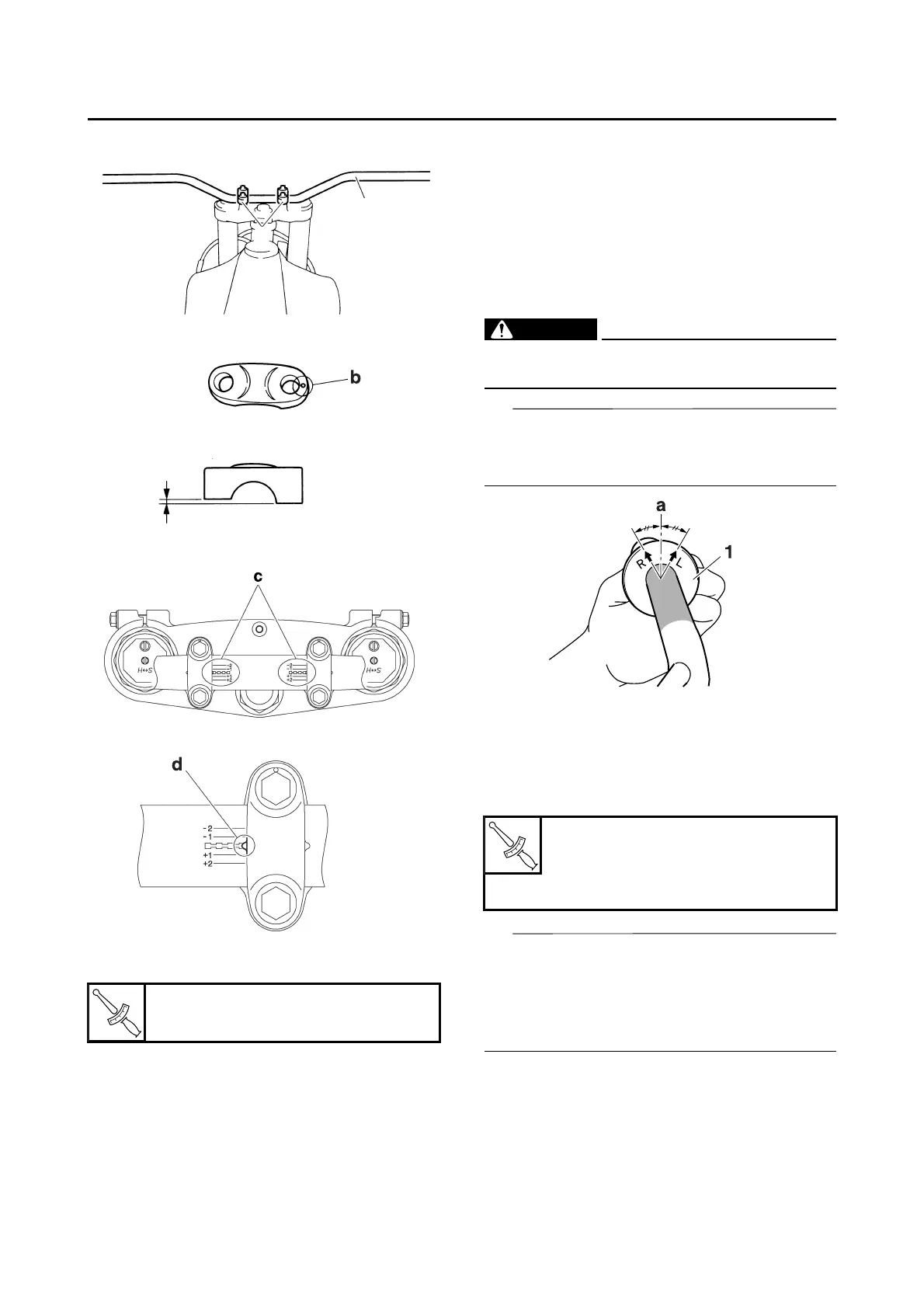
3. Tighten:
• Lower handlebar holder nut
4. Install:
• Handlebar grip “1”
▼▼▼▼▼▼▼▼▼▼▼▼▼▼▼▼▼▼▼▼▼▼▼▼▼▼▼▼▼▼▼▼
a. Slightly coat the handlebar left end with a
rubber adhesive.
b. Install the handlebar grip on the handlebar
by pressing the grip from the left side.
c. Wipe off any excess adhesive with a clean
cloth.
EWA13120
Do not touch and move the handlebar grip
until its adhesive dries completely.
Install the handlebar grip to the handlebar so
that the line “a” between the two arrow marks
faces straight upward.
▲▲▲▲▲▲▲▲▲▲▲▲▲▲▲▲▲▲▲▲▲▲▲▲▲▲▲▲▲▲▲▲
5. Install:
• Engine stop switch “1”
• Clutch lever “2”
• Clutch lever holder “3”
•Clamp “4”
• The engine stop switch, the clutch lever, and
the clutch lever holder should be installed ac-
cording to the dimensions shown.
• Pass the engine stop switch lead through the
middle of the clutch lever holder.
Lower handlebar holder nut
40 Nm (4.0 m·kgf, 29 ft·lbf)
Engine stop switch screw
0.5 Nm (0.05 m·kgf, 0.36 ft·lbf)
Clutch lever holder bolt
5 Nm (0.5 m·kgf, 3.6 ft·lbf)
 Loading...