OIL PUMP AND BALANCER GEAR
5-54
EAS1SM1266
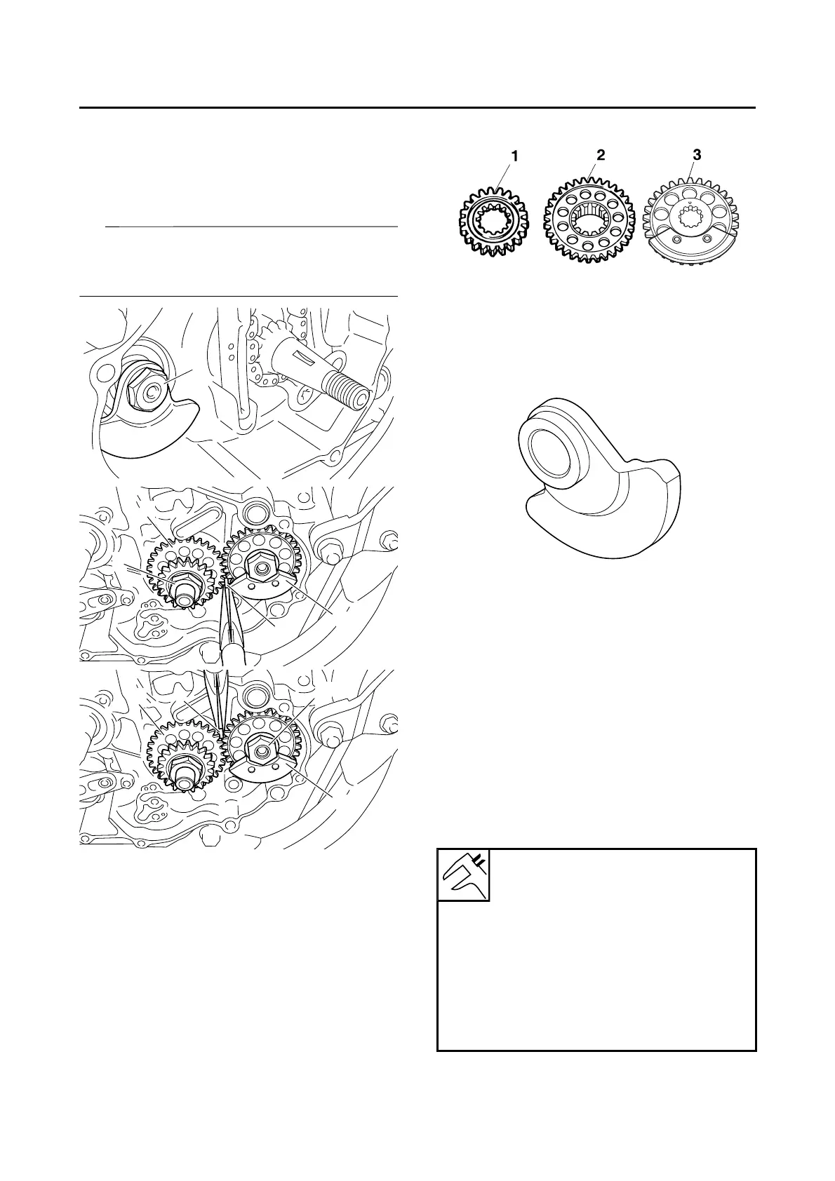
REMOVING THE BALANCER
1. Loosen:
• Balancer nut “1”
• Primary drive gear nut “2”
• Balancer weight gear nut “3”
Place an aluminum plate “a” between the teeth
of the balancer drive gear “4” and balancer
weight gear “5”.
EAS1SM1267
CHECKING THE PRIMARY DRIVE GEAR,
BALANCER SHAFT DRIVE GEAR, AND
BALANCER WEIGHT GEAR
1. Check:
• Primary drive gear “1”
• Balancer shaft drive gear “2”
• Balancer weight gear “3”
Wear/damage Replace.
EAS1SM1268
CHECKING THE BALANCER
1. Check:
•Balancer
Crack/damage Replace.
EAS1SM1269
CHECKING THE OIL PUMP
1. Check:
• Oil pump drive gear
• Oil pump driven gear
• Oil pump housing
• Oil pump housing cover
Cracks/damage/wear Replace the defec-
tive part(s).
2. Measure:
• Inner-rotor-to-outer-rotor-tip clearance “a”
• Outer-rotor-to-oil-pump-housing clearance
“b”
• Oil-pump-housing-to-inner-rotor-and-outer-
rotor clearance “c”
Out of specification Replace the oil pump.
Inner-rotor-to-outer-rotor-tip
clearance
Less than
0.150 mm (0.0059 in)
Outer-rotor-to-oil-pump-housing
clearance
0.13–0.18 mm (0.0051–0.0071 in)
Oil-pump-housing-to-inner-and-
outer-rotor
clearance
0.06–0.11 mm (0.0024–0.0043 in)
 Loading...