KICKSTATER
5-45
EAS1SM1249
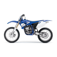
REMOVING THE KICK SHAFT ASSEMBLY
1. Remove:
• Kick shaft assembly “1”
Unhook the torsion spring “2” from the hole “a”
in the crankcase.
EAS1SM1250
CHECKING THE KICK SHAFT AND RATCH-
ET WHEEL
1. Check:
• Ratchet wheel “1” smooth movement
Unsmooth movement Replace.
• Kick shaft “2”
Wear/damage Replace the kick shaft as-
sembly.
• Spring “3”
Broken Replace.
EAS1SM1251
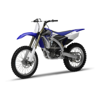
CHECKING THE KICK GEAR, KICK IDLE
GEAR, AND RATCHET WHEEL
1. Check:
• Kick gear “1”
Wear/damage Replace the kick shaft as-
sembly.
• Kick idle gear “2”
• Ratchet wheel “3”
• Gear teeth “a”
• Ratchet teeth “b”
Wear/damage Replace.
EAS1SM1252
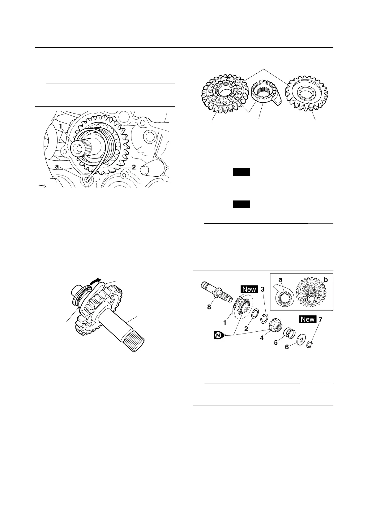
INSTALLING THE KICK SHAFT ASSEMBLY
1. Install:
• Kick gear “1”
• Washer “2”
• Circlip “3”
• Ratchet wheel “4”
• Spring “5”
• Washer “6”
• Circlip “7”
(to the kick shaft “8”)
• Apply molybdenum disulfide oil to the inner
circumferences of the kick gear and ratchet
wheel.
• Align the punch mark “a” on the ratchet wheel
with the punch mark “b” on the kick shaft.
2. Install:
• Torsion spring “1”
(to the kick shaft “2”)
Make sure the stopper “a” of the torsion spring
fits into the hole “b” on the kick shaft.
 Loading...