OIL PUMP AND BALANCER GEAR
5-55
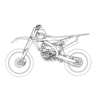
3. Check:
• Oil pump operation
Rough movement Repeat steps (1) and
(2) or replace the defective part(s).
EAS1SM1270
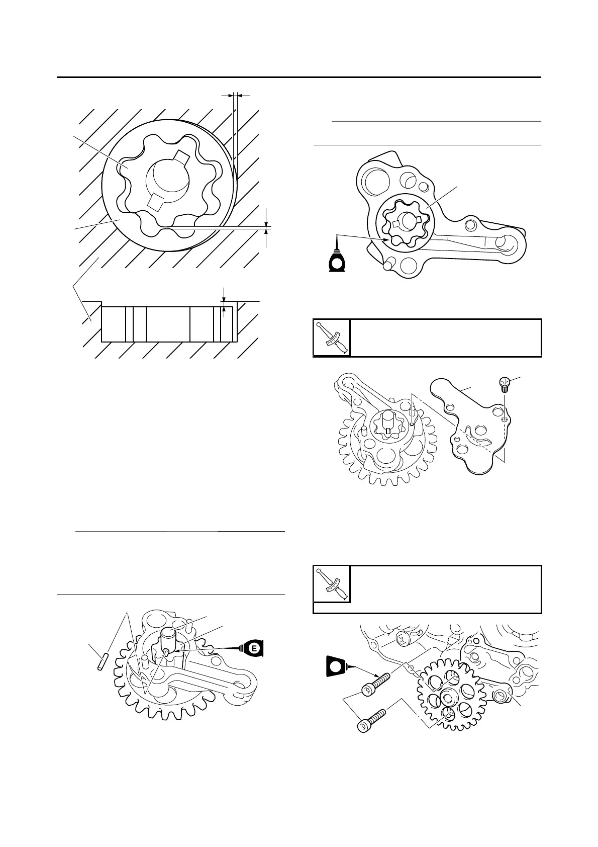
ASSEMBLING THE OIL PUMP
1. Install:
• Oil pump drive shaft “1”
• Inner rotor “2”
• Dowel pin “3”
• Apply the engine oil on the oil pump drive
shaft and inner rotor.
• Fit the dowel pin into the groove in the inner
rotor.
2. Install:
• Outer rotor “1”
Apply the engine oil on the outer rotor.
3. Install:
• Oil pump cover “1”
• Oil pump cover screw “2”
EAS1SM1271
INSTALLING THE OIL PUMP AND BALANC-
ER GEAR
1. Install:
• Oil pump assembly “1”
• Oil pump assembly bolt “2”
ECA1DX1023
1. Inner rotor
2. Outer rotor
3. Oil pump housing
Oil pump cover screw
2.0 Nm (0.20 m·kgf, 1.4 ft·lbf)
Oil pump assembly bolt
5 Nm (0.5 m·kgf, 3.6 ft·lbf)
LOCTITE®
 Loading...