EAS1SM1006
HOW TO USE THIS MANUAL
In this manual, descriptions of installation, removal, disassembly, assembly, check, and adjustment
procedures are laid out with the individual steps in sequential order.
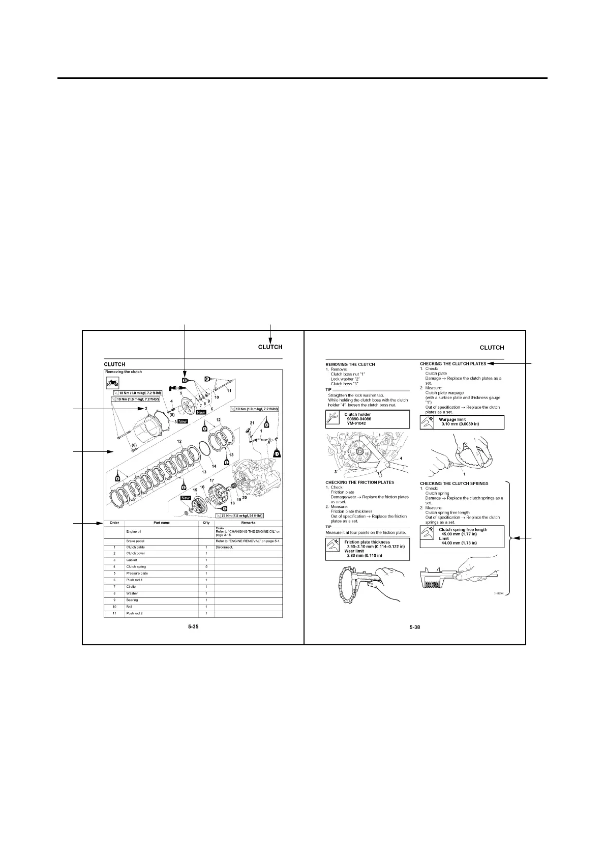
• The manual is divided into chapters and each chapter is divided into sections. The current section
title “1” is shown at the top of each page.
• Sub-section titles “2” appear in smaller print than the section title.
• To help identify parts and clarify procedure steps, there are exploded diagrams “3” at the start of
each removal and disassembly section.
• Numbers “4” are given in the order of the jobs in the exploded diagram. A number indicates a re-
moval or a disassembly step.
• Symbols “5” indicate parts to be lubricated or replaced.
Refer to “SYMBOLS”.
• A job instruction chart “6” accompanies the exploded diagram, providing the order of jobs, the
names of parts, the notes in jobs, etc.
• Jobs “7” requiring more information (such as special tools and technical data) are described se-
quentially.

 Loading...