I-2649a (4/4)
ARH: 100 y 125
ARC: 100 y 125
SP-1
B21
1 2 3 4 5 6 7 8 9 10 11 12 13
14 15 16
S4
+ + + +
S4
17 18 19 20 21 22 24 25 26
EEV-1
EEVC-1
EEVC-2
SP-2
B22
1 2 3 4 5 6 7 8 9 10 11 12 13
14 15 16 17 18 19 20 21 22 24 25 26
EEV-2
R
x2
24V
B
33 34 35 3630 31 32
a b c d a b
b acb ac
c d
a White c Red
b Black d Green
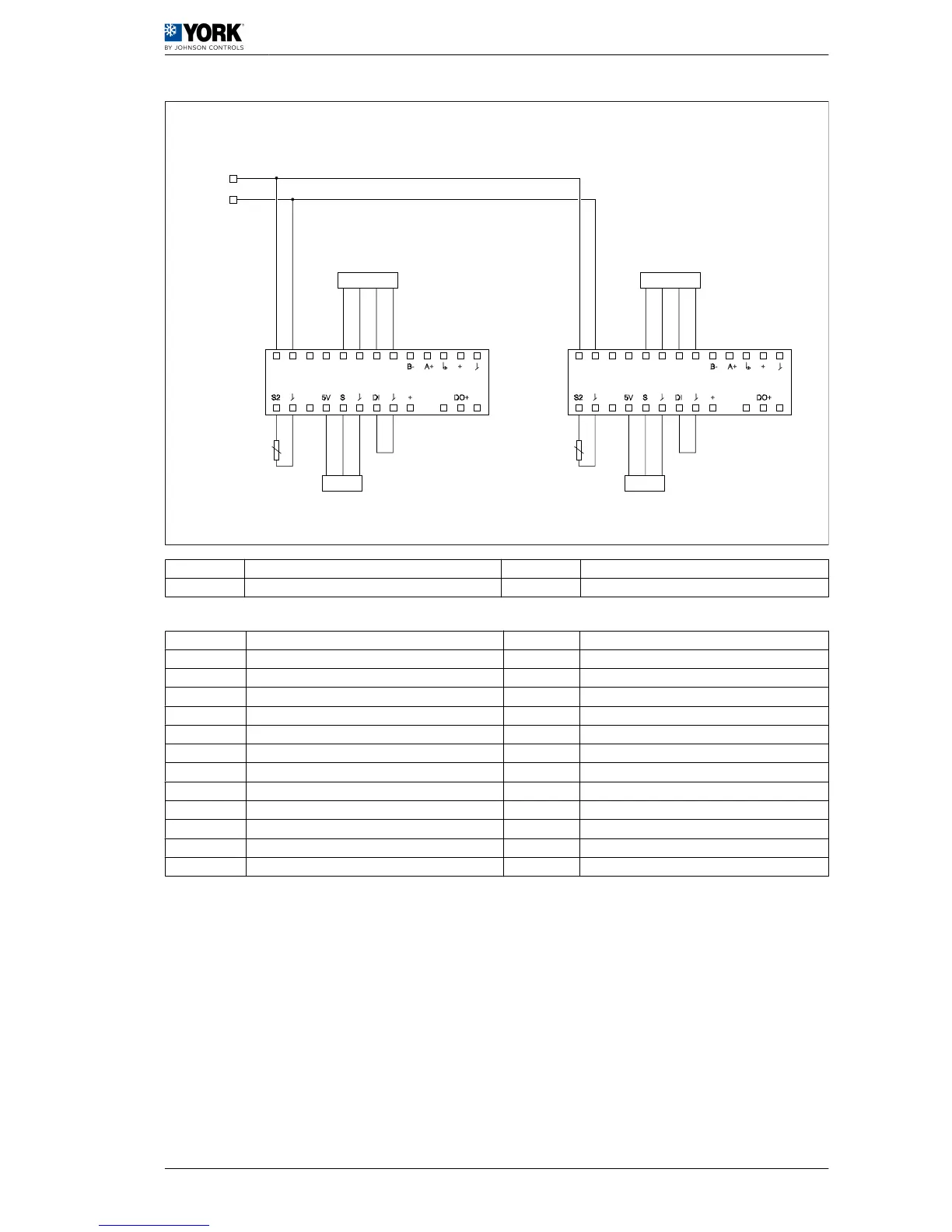
A S1 configuration on A1 board (VCH models) N High and low pressure switch 2
B Thermostat O Outdoor fan motor trip switch 2
C Electronic board [A1] P 4-way valve 2
D Compressor 2 a Black connector
E YKTOOL connection b Green connector
F RS-485 connection c White connector
G Shielded cable, 10 x 0,22 mm
2
d Yellow connector
H Electronic board [A2] e Red connector
I Accessories connection B1, B5 Suction probe
J Indoor fan motor trip switch B2, B6 Liquid probe
K High and low pressure switch 1 B3, B7 Discharge probe
L Outdoor fan motor trip switch 1 B4 Outdoor probe
M 4-way valve 1 B8 Supply probe
Wiring diagrams 4
ARC/ARH 100 – 125 wiring diagrams 4.5
61
 Loading...