Model
Q2
[A]
B F1 [A] F2 [A] F3 [A] F4 [A]
F5 [A]
REG.
F6 [A]
REG.
F7, F8
[A]
REG.
F9, F10
[A]
REG.
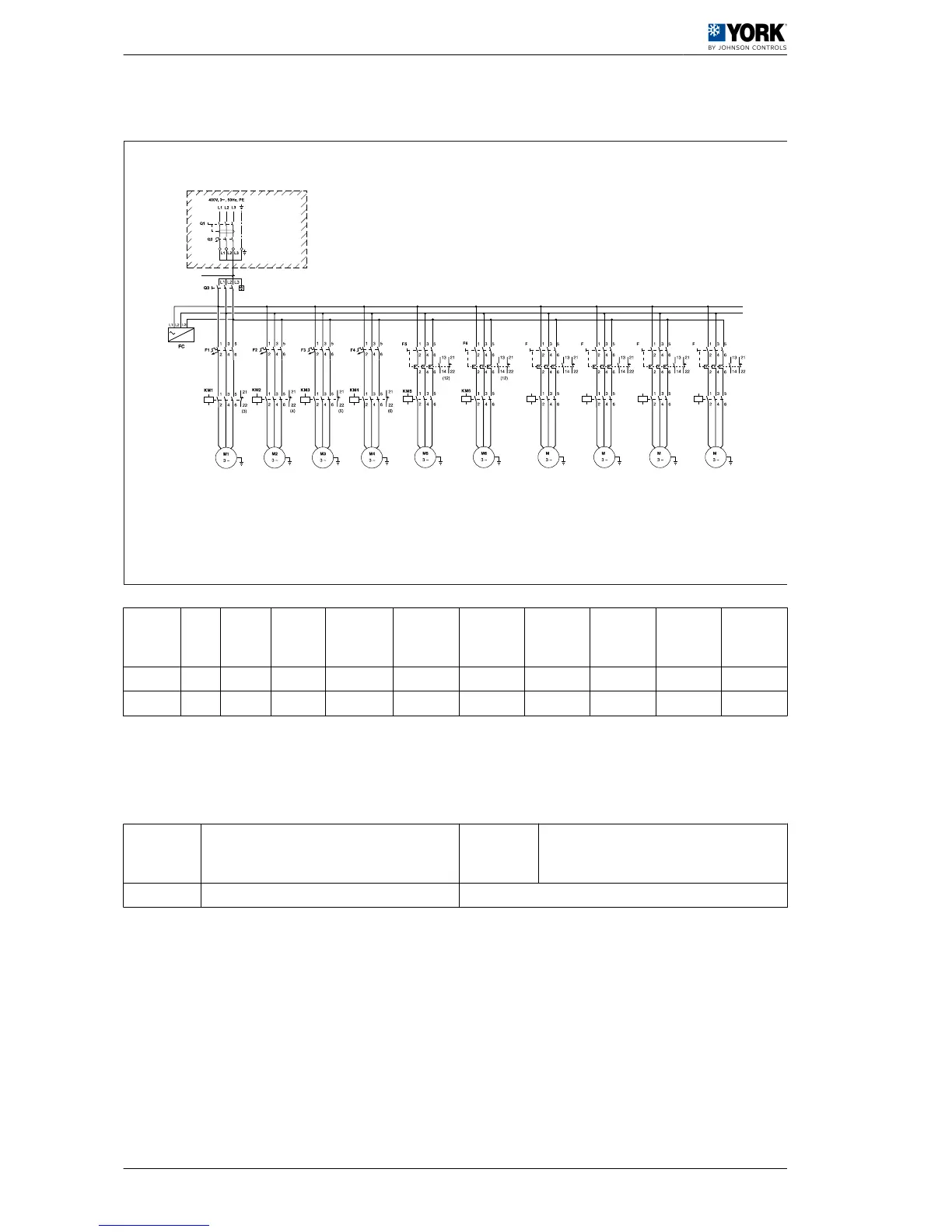
150 160 3 x 50 32 32 32 32 9,5 9,5 4,2 4,2
175 200 3 x 70 32 32 32 32 9,5 9,5 4,2 4,2
( * )
If the unit has power and the green LED V2 on board A1 is off, check that the sequence of
phases L1, L2, L3 is correct.
A
On-site installation. These compo‐
nents are not supplied by the manufac‐
turer
FC Phase control
B Cross-section B [mm
2
]
4 Wiring diagrams
4.6 ARC/ARH 150 – 175 wiring diagrams
62
 Loading...