84
YORK INTERNATIONAL
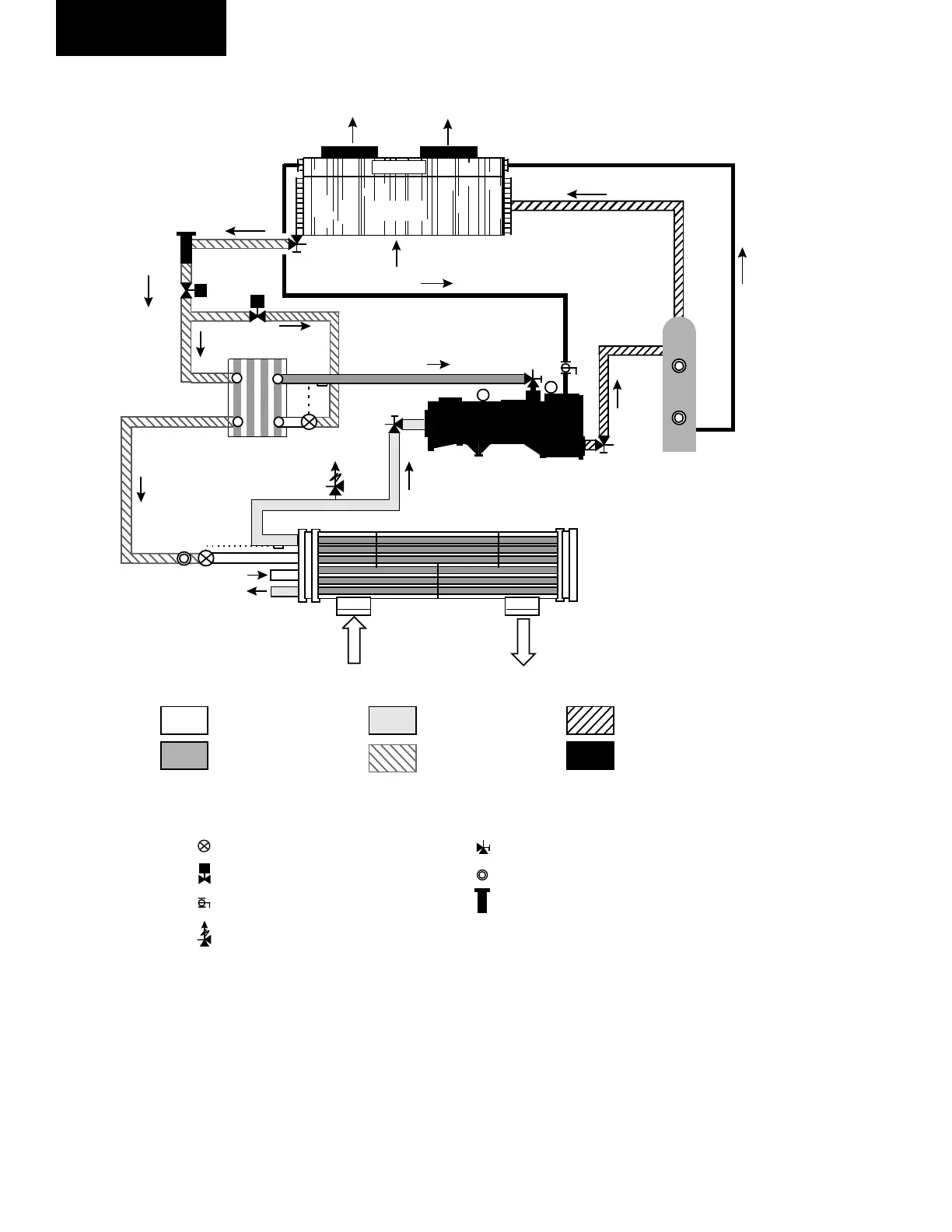
Low Pressure Liquid
Medium Pressure Vapour
Low Pressure Vapour
High Pressure Liquid
High Pressure Vapour
Oil
COMP - Compressor CDR -Condenser Coil CLR - Cooler EC - Economizer (Added to some models)
OC - Oil Cooler OS - Oil Separator
- Air Entering Compressor R-22 - Refrigerant Circuit Number
Thermostatic Expansion ValveSolenoid Valve
Balance Valve
Relief Valves
Angle Stop Valve
Sight Glass
Replaceable Core Filter Drier
Solenoid Valve
CH.W
CH.W
CLR
RC2
EC
COMP.
OS
CDR
OC
m /s
3
m /s
3
REFRIGERANT FLOW DIAGRAM
Low pressure liquid refrigerant enters the cooler and is
evaporated and superheated by the heat energy absorbed
from the chilled water passing through the cooler shell.
Low pressure vapor enters the compressor where pres-
sure and superheat are increased. High pressure vapor is
passed through the oil separator where compressor oil is
removed and recirculated to the compressor via the oil
cooler. The high pressure oil-free vapor is fed to the Air-
cooled condenser coil and fans where the heat is removed.
The fully condensed liquid enters the economizer.
A small percentage of the of the liquid passes through
an expansion valve, into the other side of the econo-
mizer where it is evaporated. This low pressure liquid
subcools the major part of the refrigerant. Medium pres-
sure vapor then returns to the compressor. The subcooled
refrigerant then passes through the expansion valve
where pressure is reduced and further cooling takes
place before returning to the cooler.
LD05009
FIG. 30 – REFRIGERANT FLOW DIAGRAM
Technical Data
 Loading...


