YORK INTERNATIONAL
118
FORM 150.62-NM7 (103)
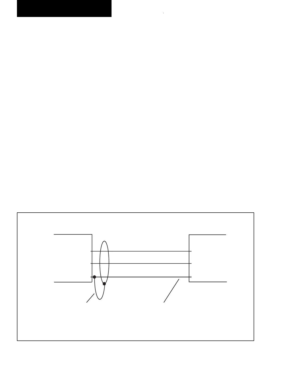
Chiller Microboard
TB2
TXD
DSR
GND
2 RD
5 CTS
7 SG
Printer
Do not connect
shield at printer end
Shield (connect shield to Pin 5
of the connector)
LD03843
The micro panel is capable of supplying a print out of
chill er conditions or fault shutdown in for ma tion at any
given time. This allows operator and service per son nel
to obtain data and system status with the touch of the
keypad. In ad di tion to manual print selection, the micro
panel will pro vide an automatic printout when ev er a
fault occurs. De tailed ex pla na tion of the print function
is giv en under “Print Key” located in the Keypad and
Dis play sec tion.
YORK recommends the fi eld tested WEIGH-TRONIX
model 1220 printer (or former IMP 24). This is a com-
pact low cost printer that is ideal for service work and
data logging.
The WEIGH-TRONIX printer can be obtained by con-
tact ing WEIGH-TRONIX for purchase in for ma tion at:
WEIGH-TRONIX
2320 Airport Blvd.
Santa Rosa, CA 95402
Phone: 1-800-982-6622 or 1-707-527-5555
(International Orders Only)
The part number for the printer that is packaged spe cifi -
cal ly for YORK is P/N 950915576. The cable to connect
the printer can either be locally assembled from the parts
listed, or ordered directly from WEIGH-TRONIX under
part num ber 287-040018.
Parts
The following parts are required:
1. WEIGH-TRONIX model 1220 printer.
2. 2.25" (5.7cm) wide desk top calculator paper.
3. 25 ft. (7.62m) maximum length of Twisted Pair
Shield ed Cable (minimum 3 con duc tor), #18 AWG
stranded, 300V min i mum in su la tion.
4. One 25 pin Cannon connector and shell.
Connector: Cannon P/N DB-25P or equiv a lent.
Shell: Cannon P/N DB-C2-J9.
Assembly and Wiring
All components should be assembled and wired as
shown in Figure 16. Strip the outside in su la tion back
sev er al inches and individual wires about 3/8" (9.5 mm)
to con nect the cable at the Microboard. Do not connect
the shield at the printer-end of the cable.
Obtaining a Printout
A printout is obtained by pressing the “PRINT” key on
the keypad and then pressing either the “OPER DATA”
key or “HISTORY” key.
FIG. 15 – PRINTER TO MICROBOARD ELECTRICAL CONNECTIONS
OPTIONAL PRINTER INSTALLATION
Service and Trou ble shoot ing
 Loading...


