YORK INTERNATIONAL
97
FORM 150.62-NM7 (103)
2
As an example of com pres sor staging (refer to Table 34),
a chill er with six com pres sors using a Cool ing Set point
pro grammed for 45°F (7.20°C) and a Range Set point
of 10°F (5.56°C). Using the formulas in Table 24, the
con trol range will be split up into six (sev en in clud ing
hot gas) seg ments, with the Control Range de ter min ing
the separation between segments. Note also that the
Cool ing Setpoint is the point at which all com pres sors
are off, and Cooling Setpoint plus Range is the point
all com pres sors are on. Spe cifi cal ly, if the return water
tem per a ture is 55°F (12.8°C), then all com pres sors
will be on, pro vid ing full capacity. At nom i nal gpm, this
would pro vide ap prox i mate ly 45°F (7.2°C) leaving water
tem per a ture out of the evap o ra tor.
If the return water temperature drops to 53.4°F (11.9°C),
one com pres sor would cycle off leaving fi ve com pres -
sors running. The compressors would con tin ue to cy cle
off ap prox i mate ly every 1.7°F (.94°C), with the ex cep tion
of hot gas bypass. Notice that the hot gas bypass would
be available when the return water temperature dropped
to 46.25°F (7.9°C). At this point one com pres sor would
be running.
Should the return water temperature rise from this point
to 46.7°F (8.2°C), the hot gas bypass would shut off, still
leaving one compressor running. As the load in creased,
the compressors would stage on every 1.7°F (.94°C).
Also notice that Tables 23, 24 and 25 not only provide
the for mu las for the loading (ON POINT) and un load ing
(OFF POINT) of the system, the “STEP” is also shown
in the tables. The “STEP” is that sequence in the ca-
pac i ty con trol scheme that can be viewed under the
OPER DATA key. Please refer to the section on the
DIS PLAY/PRINT keys for specifi c information on the
OPER DATA key.
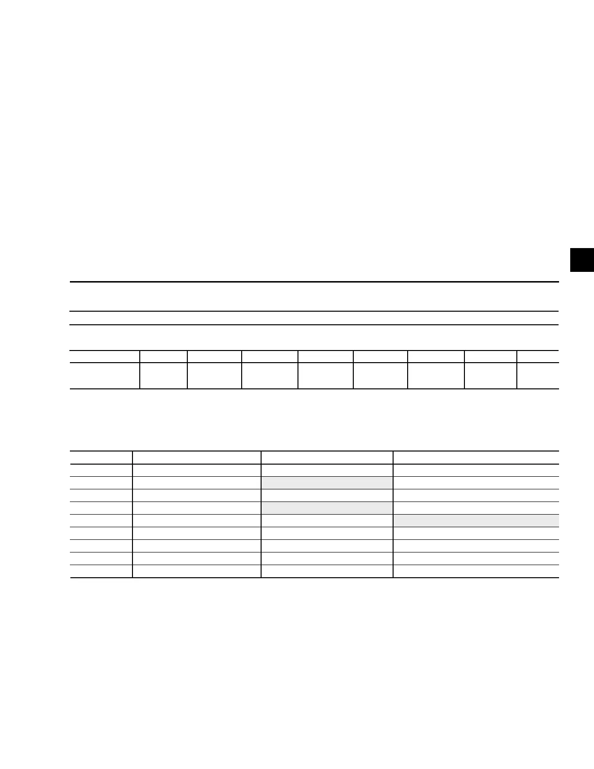
TABLE 23 – COMPRESSOR STAGING FOR RETURN WA TER CONTROL
*Unloading only
COMPRESSOR STAGING FOR RETURN WATER CONTROL
6 COM PRES SORS
COOLING SETPOINT = 45°F (7.2°C) RANGE = 10°F (5.6°C)
# OF COMP ON 0 *1+HG 1 2 3 4 5 6
RWT
45°F 46.25°F 46.7°F 48.3°F 50.0°F 51.7°F 53.4°F 55.0°F
(7.2°C) (7.9°C) (8.2°C) (9.1°C) (10.0°C) (11.0°C) (11.9°C) (12.8°C)
TABLE 24 – RETURN CHILLED LIQUID CONTROL FOR 5 & 6 COMPRESSORS (7 & 8 STEPS)
*STEP COMPRESSOR COMPRESSOR ON POINT COMPRESSOR OFF POINT
0 0 SETPOINT SETPOINT
1 1 W/HGB SP + CR/8 (Note 1) SETPOINT
2 1 NO HGB SP + CR/6 SETPOINT
3 2 SP + 2*CR/6 (Note 2) SP + CR/6
4 2 SP + 2*CR/6 SP + CR/6 (Note 3)
5 3 SP + 3*CR/6 SP + 2*CR/6
6 4 SP + 4*CR/6 SP + 3*CR/6
7** 5 SP + 5*CR/6 SP + 4*CR/6
8 6 SP + CR SP + 5*CR/6
NOTES:
1. Step 1 is Hot Gas Bypass and is skipped when loading occurs. Hot Gas Bypass op er a tion is inhibited during Pumpdown.
2. Step 3 is skipped when loading occurs.
3. Step 4 is skipped when unloading occurs.
* STEP can be viewed using the OPER DATA key and scrolling to COOLING DEMAND.
** 5-Compressor Chillers stop at 7 steps
 Loading...


