161
JOHNSON CONTROLS
FORM 201.21-NM1 (1223)
6
Two 8 channel, 8 bit Digital to Analog Converters (D/A
Converter) on the Chiller Control Board supply the Feed
and Drain Valve Controller signals to allow the controller
to position the Flash Tank Feed and Drain Valves. The
Feed Valve controls the refrigerant level in the ash tank
while the Drain Valves controls superheat. The control
voltage to the Feed and Drain Valve Controller has a
range of 0-10.28 VDC.
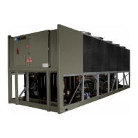
RELAY OUTPUT BOARDS
LD10607
Two or three Relay Output Boards are required to
operate the chiller. These boards convert 0-12VDC
logic levels outputs from the Chiller Control Board
to 115VAC levels used by contactors, relays, solenoid
valves, etc., to control system and chiller operation. The
common side of all relays on the Relay Output Board is
connected to +12VDC.
The open collector outputs of the Chiller Control Board
energize the DC relays on the Relay Output Board
by pulling one side of the relay coil to ground. When
not energized, both sides of the relay coils will be at
+12VDC potential.
VSD (Variable Speed Drive)
The VSD is a liquid cooled, transistorized, PWM
inverter packaged within the Control/Power cabinet.
The inverter is composed of four major sections: the AC
to DC rectier section with precharge circuit, a DC link
lter section, a three phase DC to AC inverter section,
and an output RC suppression network.
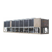
AC TO DC RECTIFIER
The AC to DC Rectier circuit utilizes a semi-converter
made of three SCR/diode modules in a three phase
bridge conguration. Each SCR/Diode module contains
1 SCR and 1 diode. The modules are mounted on a
liquid cooled heatsink. This circuit rectifies the
incoming AC voltage to unltered DC, which is ltered
by the DC Link Filter.
A semi-converter (combination SCR/Diode)
conguration allows utilizing a separate pre-charge
circuit to limit the current in the DC link lter capacitors
when the VSD is rst switched on. This is accomplished
by slowly turning on the SCR’s to initially charge the
DC Bus. Once charged, the SCR’s remain fully gated
on during normal operation. This conguration also
provides a fast disconnect from main power when the
drive is switched o.
When the drive is called to run (leaving chilled liquid
temperature is > than the Setpoint + CR), the SCR/Diode
modules are turned on by the SCR trigger Board, allow-
ing the DC link lter capacitors to slowly precharge for
a period of 20 seconds.
The AC incoming line voltage is rectied by the full
three phase semi-converter bridge, made up of three
SCR/Diode modules, which provides pulsating DC to
the DC link Filter in the VSD.
CHILLER ELECTRONIC COMPONENTS (CON'T)
LD10608
 Loading...