162
JOHNSON CONTROLS
FORM 201.21-NM1 (1223)
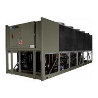
SCR TRIGGER BOARD
The SCR Trigger Board controls the ring (gating)
sequence of the Bridge SCR’s.
TECHNICAL DATA
CHILLER ELECTRONIC COMPONENTS (CON'T)
Command for the SCR Trigger Board to begin ring the
SCR’s is initiated by the VSD Logic Board.
The SCR Trigger Board also monitors the three phase
input voltage to detect the loss of an incoming phase.
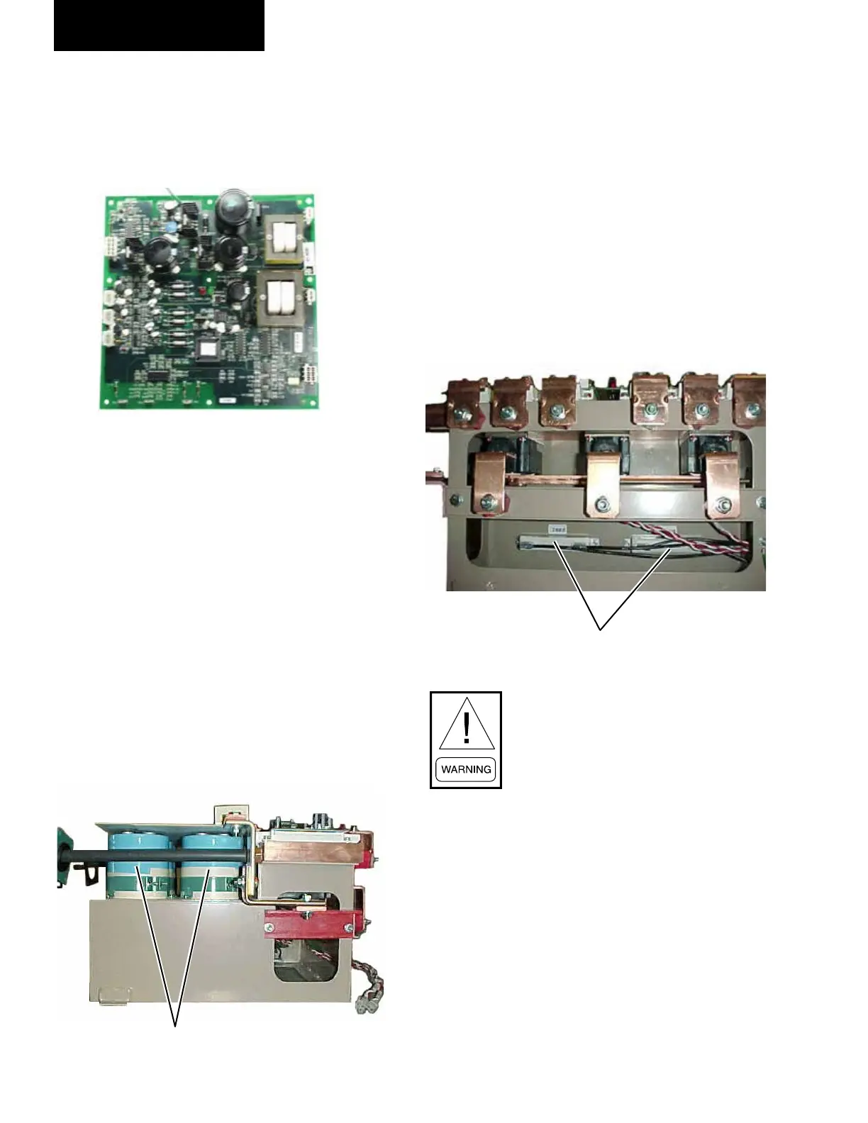
DC LINK FILTER
The DC Link Filter consists of a bank of electrolytic
lter capacitors. The capacitors smooth (lter) ripple
voltage resulting from the AC to DC rectication and
provides an energy reservoir for the DC to AC inverter.
The capacitor lter bank is made up of 2 banks of
parallel-connected capacitors wired in series. Series
banks of capacitors allow using smaller sized capacitors
with lower voltage ratings.
FILTER
CAPACITORS
The capacitor bank in conjunction with the 1L line
inductor forms a low pass LC Filter and provides further
smoothing (lters ripple) to the rectied DC.
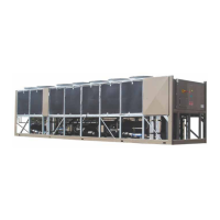
Equalizing/Bleeder resistors connected across the
banks equalize the voltage between the top and bottom
capacitors to avoid damaging the capacitors from over
voltage. The Equalizing/Bleeder resistors also provide
a path for discharge of the capacitors when the drive is
switched o. This safely discharges the capacitors in
approximately 5 minutes. Always be careful, a bleeder
resistor could be open and the bus may be charged.
When servicing, always check the
DC Bus Voltage across the top and
bottom, banks of capacitors with
a known functioning voltmeter
correctly set to the proper scale before
performing service on the inverter. DO
NOT rely on the Bleeder Resistors to
discharge the capacitor banks without
checking for the purpose of safety.
NEVER short out a capacitor bank
to discharge it during servicing. If a
bleeder resistor is open and a capacitor
bank will not discharge, immediately
contact YORK Product Technical Sup-
port.
LD10609
LD10610
LD10611
EQUALIZING/BLEEDER
RESISTORS
 Loading...