2626
YHVP-ECM
YHVP-ECM Serie
For this fan coil configuration, the 1-10 Vdc signal, which controls the inverter, must be supplied by a controller with the following
signal specifications:
• Impedance < 100 Ohm;
• Maximum speed 10 Vdc;
• Fan OFF with V < 1 Vdc;
• Signal 1 - 10 Vdc.
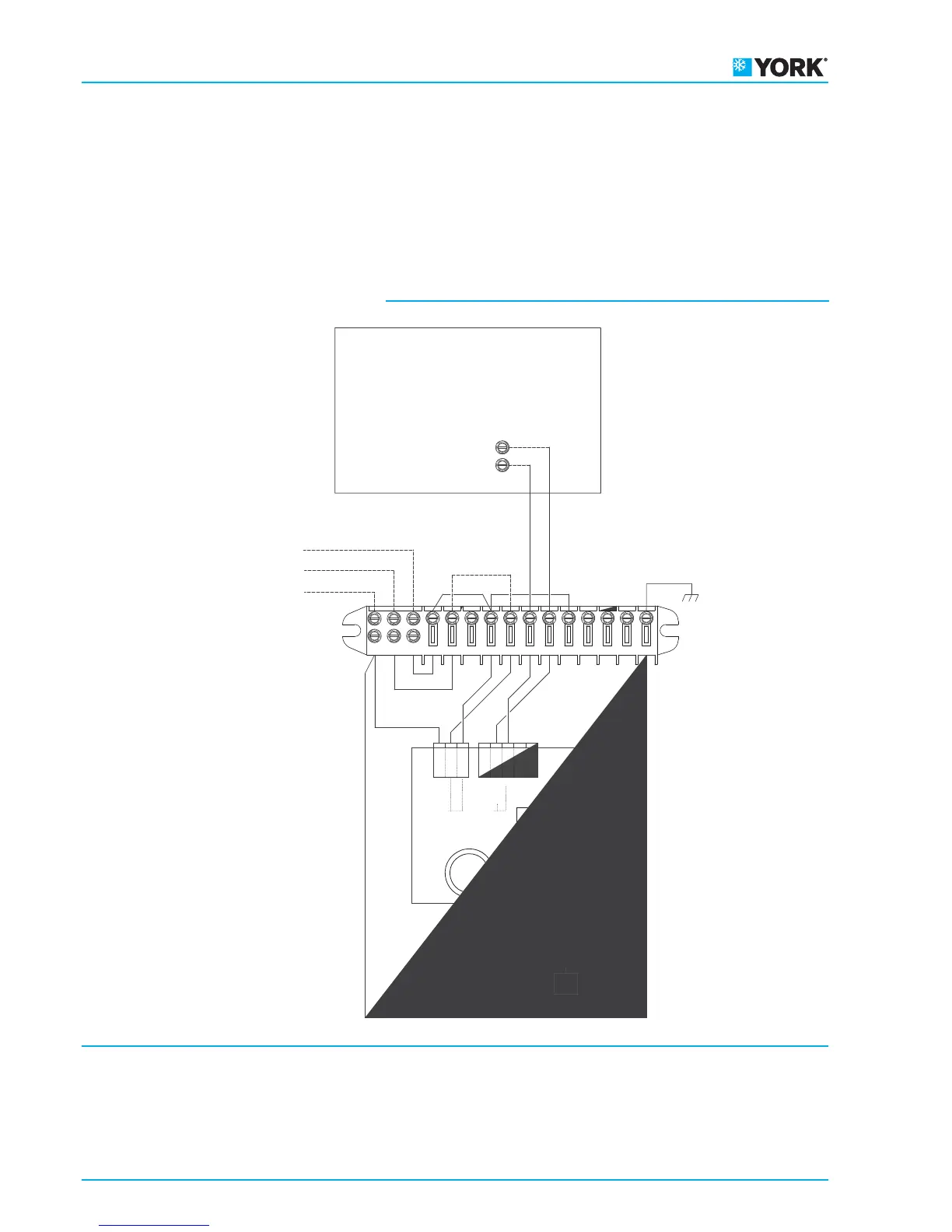
YHVP–ECM electric wiring diagram
Legend
CONTROLLER = Controller
BLAC = Inverter circuit board
M = Brushless electronic motor
CM = Motor fan connection
CP = Motor fan thermal protection connection
ECM configuration
PE
97
15
N
ECM board
power supply
0-10Vdc
Input signal
W
V
U
N
11
14
1210
13
45
8
MFC
M
6
0
Vdc
10
Vdc
CONTROLLER
L
L
Tp
Tp
PE
A+
P-
0
10VDC
P15V
P+
A-
3
N
230Vac 50Hz
PE
BLAC
L
CM
CP
 Loading...