Communication with Modbus
A43/A44 140 2CMC48001M0201
User Manual Revision: C
9.9 Load profile
Mapping table
Structure of
the header
Note – Before you can use the information in this chapter you must be familiar with
and understand the information and the concepts described in “Historical Data” on
page - 114.
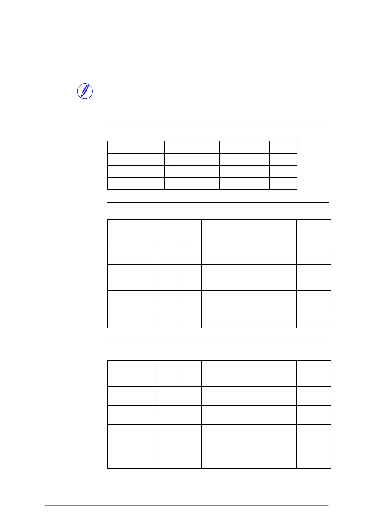
The following table shows an overview of the mapping table:
The following table describes the header:
Write value 1 to this register to load
the next block of load profile entries
Write to this register to choose a
load profile channel. Possible values
Write to this register to choose a
date/time to start reading from
Write to this register to choose the
Structure of
the channel
information
The following table describes the channel information registers:
OBIS code for the quantity stored in
Scaling of the values stored in this
Interval with which values are stored
in this channel. Expressed in
Data type of the values stored in this

 Loading...


