Communication with Modbus
2CMC48001M0201 153 A43/A44
Revision: C User Manual
Step Action
6 Repeat step 1 to 4 for all alarms.
9.10.5 Inputs and outputs
General
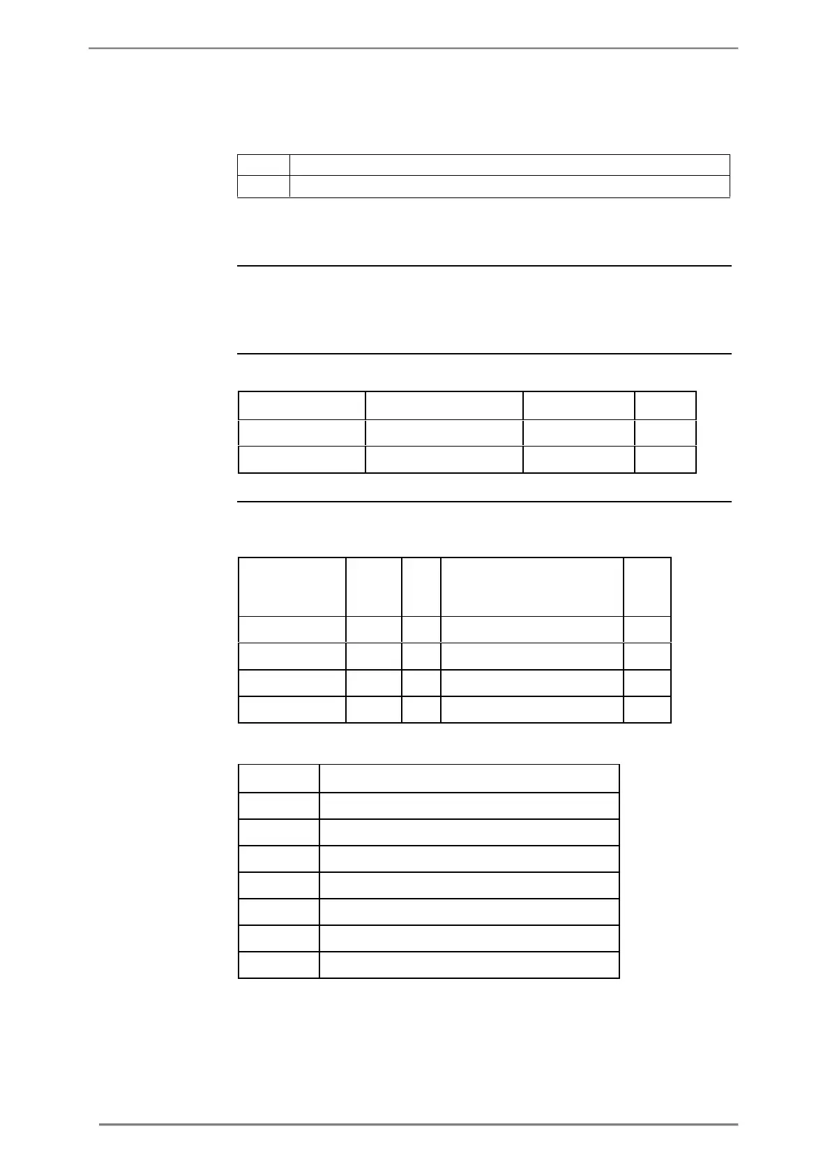
Mapping table
I/O port
configuration
registers
Inputs and outputs configuration defines the function for each physical I/O port.
It also defines the parameters for the logical pulse outputs.
The following table shows an overview of the mapping table:
Pulse output configuration
The following table describes the group of registers for configuring the
function for physical I/O ports:
Function of first I/O port
Function of second I/O port
Function of third I/O port
Function of fourth I/O port
The following table lists the possible values for I/O port function:

 Loading...


