Home
ABB
Controller
AC 31
ABB AC 31 User Manual
4
of 1
of 1 rating
221 pages
Give review
Manual
Specs
To Next Page
To Next Page
To Previous Page
To Previous Page
Loading...
Presentation / operation
Page 2-14
ABB Contro
l - AC 31
1SBC 260400 R1001-b
06.99
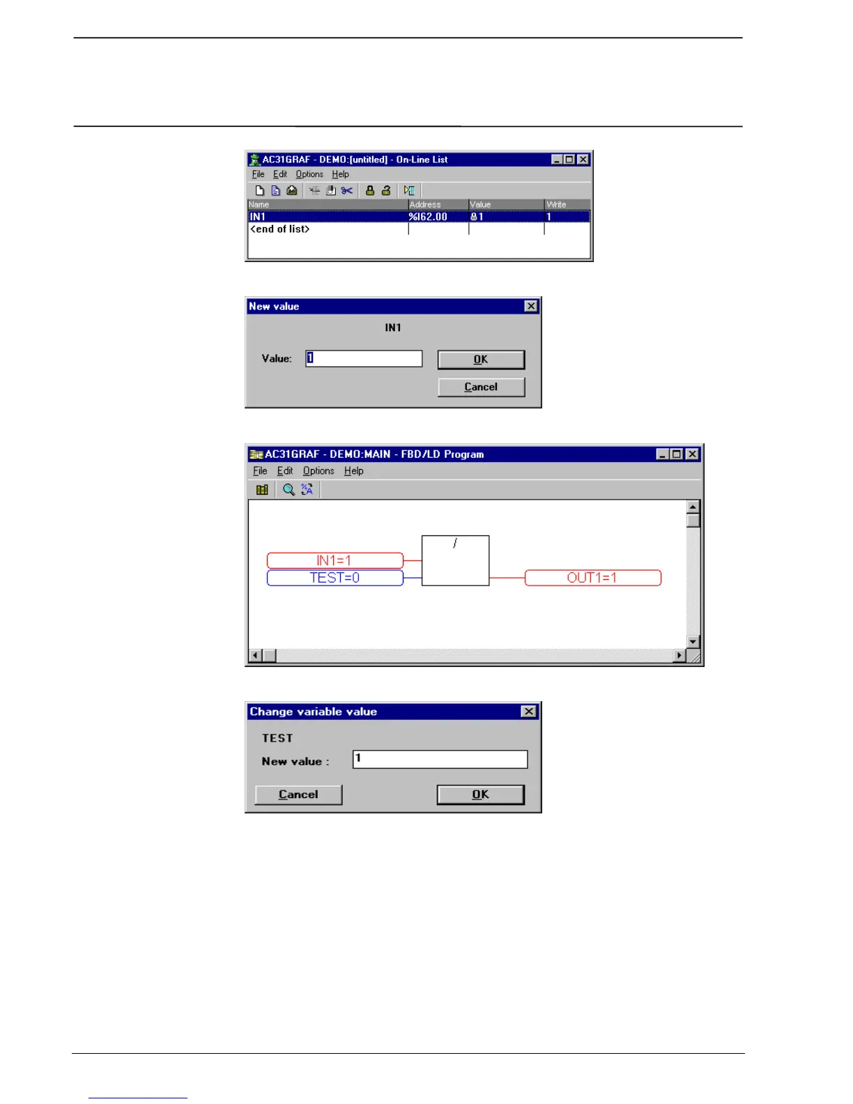
Figure 2-21 :
"O
n-line List"
Figure 2-22 : Forcing the input to 1
Figure 2-23 : The software result of the input forcing
Figure 2-24 : Changing the v
ariable value to 1
40
42
Table of Contents
Default Chapter
2
Table of Contents
2
Chapter 1
8
Presentation / Operation
8
Presentation
9
General Setup Rules
10
Central Units with Extensions
12
Central Units with CS 31 Bus
12
Cabling Techniques
12
Operation of the 40 and 50 Series Central Units
14
Functional Diagram
14
Program Execution
16
Bus Transmission
16
Refresh Times / Reply Times
17
Bus Refresh Times
17
Central Unit Reply Times
17
Power on / Program Launch
18
Power Cuts or Drops
19
References
20
Chapter 2
28
Getting Started
28
Required Material
30
Cabling
30
Programming
32
Launching the AC31GRAF Software
32
Project Creation
32
Variable Declarations
34
Program Editing
34
Displaying the FBD (Function Blocks) Toolbar
34
Selecting the or Function in the Program Editor Window
34
Inserting Variables
36
Links between the Variables and the Function Block
36
Saving
36
Compilation
36
Communication with the PLC
38
Configuration of the Serial Interface
38
Access to the Control Panel
38
Configuration of the Central Unit
38
Initializing the Central Unit
40
Sending the Program to the PLC
40
On-Line Program Tests
40
Quitting AC31GRAF
42
Chapter 3
44
Technical Specifications
44
General Operating Conditions
46
CS 31 Bus Technical Specifications
48
Central Units
50
The Front of the Central Unit (See Figure 3-1)
50
Technical Specification
51
Extensible Remote Units
56
The Front (See Figure 3-3)
56
Technical Specifications of the Extensible Remote Units
57
Binary Extensions
60
The Front (See Figure 3-5 to Figure 3-9)
60
Binary Extensions Specifications
61
Analog Extensions
64
The Front (See Figure 3-10, Figure 3-11)
64
Analog Display (See Figure 3-12)
64
Technical Specifications of the Analog Extension
65
Analog Inputs Diagram
67
Current 4-20Ma
67
Current 0-20Ma
67
Pt100/Pt1000
67
Analog Outputs Diagrams
68
Current 0-20Ma
68
Current 4-20Ma
68
Accessories
70
Programming Cables: 07 SK 50 and 07 SK
70
SK 50 Connection Diagram (See Figure 3-13)
70
SK 52 Connection Diagram (See Figure 3-14)
72
ASCII/MODBUS ® Communication Cables: 07 SK 51 and
74
SK 51 Connection Diagram (See Figure 3-15)
74
SK 53 Connection Diagram (See Figure 3-16)
76
TC50 Display Cables: 07 SK 54 and 07 SK
78
Connectors (See Figure 3-17)
78
External Dual Connector: 07 ST
78
Cage-Clamp" Type Connectors
78
External Dual Connector: 07 ST
80
Stickers
81
TC50 Display
81
Dimensions (in MM)
82
Chapter 4
84
Installation
84
Implementation of an AC 31 System
86
Assembly Conditions
86
Input/Output Cabling
86
Earthing
88
Basic Earthing Principles
88
Earthing Principles for Numerous Cabinets
88
Cabling of the CS 31 Bus
90
Different Power Supply Types
92
Central Unit and Remote Unit Cabling
94
Power Supply
94
Inputs/Outputs Cabling
94
Output Protection
94
Cabling Binary Extensions
96
Extension XI 16 E1 (See Figure 4-18)
96
Extension XO 08 R1 (See Figure 4-20)
96
Extension XC 08 L1 (See Figure 4-22)
96
Extension XO 16 N1 (See Figure 4-19)
96
Extension XK 08 F1 (See Figure 4-21)
96
Cabling the Analog Extension
98
Extension XM 06 B5
98
Extension XE 08 B5
98
Addressing
100
Input/Output Variables
100
Addressing CU Masters or Stand-Alones with Extensions
100
Addressing Slave Central Units or Remote Extension Units on the CS 31 Bus
104
Addressing Extensible Remote Units
104
Addressing Slave Central Units
106
Addressing Example
107
Summary
108
Chapter 5
110
Programming
110
Software Introduction
111
List of Variables
113
Initialization
116
Configuration
118
AC31GRAF Configuration Tool
118
The Central Unit Operative Mode
119
Transmission/Reception Range of a Slave Central Unit
120
Data Initialization and Backup
120
Initialization /Internal Bits Backup
121
Initialization / Internal Double Word Backup
122
Initialization / Chain Step Backups
122
Initialization / Historical Values Backup
122
Central Unit Reaction to Class 3 Errors
123
Initialization of the CS 31 Bus Units
123
Communication Mode of the COM1 Serial Interface
124
Communication Parameters
126
The Central Unit Cycle Time
127
CS31 Bus Communication Times
128
Clock
134
Password
134
CS31CO Configuration Function Block
134
Analog Configuration ( Extension)
136
Hardware Configuration
136
Programming Examples
142
Practical Advice
142
Operation and
143
NAND Operation
144
Operation or
144
NOR Operation
145
Combinations of Boolean Functions
145
Timer Functions
146
TON: on Delay
147
TOF: off Delay
147
TP: Monostable (Constant)
148
Time_W
148
W_Time
148
Oscillators
149
Detecting the First Cycle with the M 255.15 Variable
150
Up/Down Counter Function
151
Scaling an Analog Value
152
Using the Potentiometers of the 40 and 50 Series
152
Processing an Analog Input
153
Chapter 6
154
Program Optimization
154
Sub-Program
156
Programming Sub-Programs
156
Calling a Sub-Program
157
Passing Parameters
158
Limits
158
Interruptions
160
Programming Interruptions
160
Validation of Interruptions
161
Performances
161
Step Motor Command
162
High Speed Counter with Value Capture, Zero Reset and Overflow Detection
164
Communication between Central Units on the CS 31 Bus
166
CS 31 Bus Addressing
166
Communication Type
166
Programming
167
Bit Transmission
167
Transmission by Word
168
Utilization of the Function Blocks
170
Chapter 7
174
Network Communication with the Incorporated MODBUS Interface
174
Protocol Description
174
Communication Configuration
176
Programming
177
MODBUS Slave Unit
177
MODBUS Master Unit
177
List of Cross References
177
Example Using the MODBUS Function
180
Reply Times for MODBUS Communication
181
Point to Point Communication with the Incorporated ASCII Interface
184
Protocol Description
184
Configuration of the Communication
184
Using the Black 07 SK 51 or 07 SK 53 Cable
184
Communication Parameters
184
Programming
185
Sending Messages
185
Receiving Messages
185
Programming Example
185
Point to Point Communication with the Programming Protocol
188
Chapter 8
192
Types of Errors Detected
192
Detection of Errors
192
Status through Software
196
Error Management through Programming
196
Description of the Diagnosis Variables
196
Correspondence Table between the Error and the Diagnosis Variable Values
198
Class Error Descriptions
199
Class 1 Error Descriptions
199
Class 2 Error Descriptions
199
Class 3 Error Descriptions
199
Class 4 Error Descriptions
200
Programming Examples
201
Example of a Reaction / Command Following a Specific Error
201
Example for Saving Numerous Errors of the same Class
202
List of Variables
205
List of Functions
208
Mapping
212
Historical Values
215
4
Based on 1 rating
Ask a question
Give review
Questions and Answers:
Need help?
Do you have a question about the ABB AC 31 and is the answer not in the manual?
Ask a question
ABB AC 31 Specifications
General
Brand
ABB
Model
AC 31
Category
Controller
Language
English
Related product manuals
ABB AC 800M
230 pages
ABB AC 800F
379 pages
ABB AC 900F
156 pages
ABB i-bus KNX AC/S 1.x.1 Series
488 pages
ABB AC500
18 pages
ABB ACS55
270 pages
ABB ACS550
310 pages
ABB ACS150
156 pages
ABB ACH 500
117 pages
ABB ACH 400
48 pages
ABB ACS 400
187 pages
ABB ACS550-01
254 pages

 Loading...


