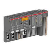
5. Plug the appropriate electronic and I/O modules in the correct locations (processor
module, communication modules on terminal base, and eventually also communication
interface modules and I/O modules onto dedicated terminal units).
6. Connect a programming cable (Ethernet cable between ETH port of CPU and PC with
engineering software).
1.5 Example project for central I/O expansion
The following steps show how to set-up an application project and configure the hardware. A
simple logic is used as example to introduce in programming and commissioning of the PLC.
The workflow for creation of a visualization is explained, as well as how to set-up a web server
for visualization.
1.5.1 Preconditions
● Automation Builder is installed and licensed as, at least, basic edition.
● AC500 V2 CPU is assembled and connected to the PC
Ä
Chapter 1.4 “Hardware AC500
V2” on page 10.
1.5.2 Create, set-up and save your AC500 V2 project
1.5.2.1 Create a project
1. Launch Automation Builder either out of the desktop icon or out of the Windows menu.
2.
Select “New Project” or go to menu “File è New Project”.
Getting started with example projects
Example project for central I/O expansion > Create, set-up and save your AC500 V2 project
2023/03/03 3ADR010649, 3, en_US 13

 Loading...