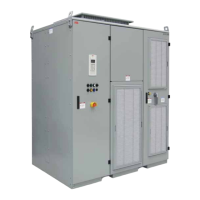
2. Select “PNIO Module I/O Mapping”.
3. Fill in the variable names:
Element Hardware channel Symbol
Switch I5 CI502 DI8 xDI_08_CI502_I5
LED output DO8 CI502 DO 8 xDO_08_CI502
1.6.4 Add remote I/O expansion to project
1.6.4.1 Add a program POU to the project
1. Double click “Application” in the device tree to create the application file.
ð
This will open the IEC 61131 programm editor CODESYS (A configuration file will
be created)
Ä
Chapter 1.5.8.1 “Starting the IEC 61131 programm editor CODESYS”
on page 40.
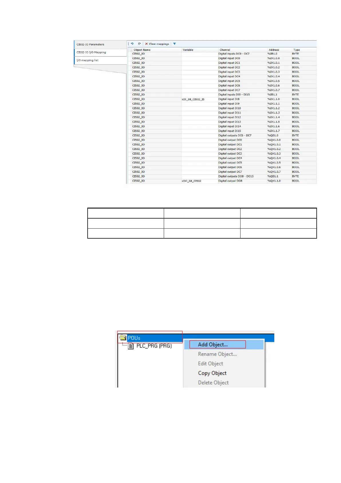
2. In the CODESYS editor device tree right-click “POUs”.
3. Select “Add object”.
4. Enter “_30_PNIO_test”.
5. Select “Program”.
6. Select Function Block Diagram “FBD”.
7. Select [OK] to add POU.
Getting started with example projects
Example project for remote I/O expansion with PROFINET > Add remote I/O expansion to project
2023/03/03 3ADR010649, 3, en_US 59

 Loading...