Actual signals and parameters
93
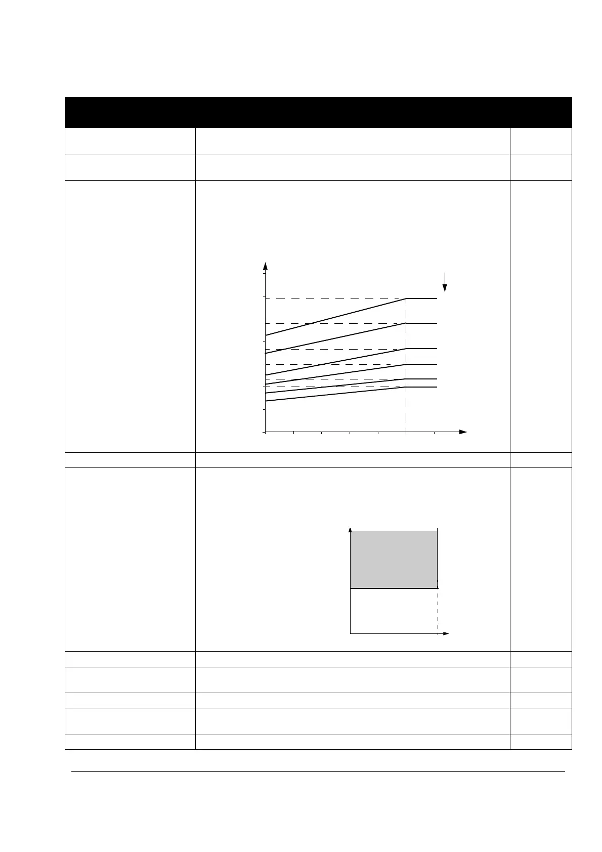
3008 ZERO SPEED LOAD Defines the load curve together with parameters 3007 MOT LOAD CURVE
and 3009 BREAK POINT FREQ.
70
25.…150% Allowed continuous motor load at zero speed in percent of the nominal motor
current
3009 BREAK POINT FREQ Defines the load curve together with parameters 3007 MOT LOAD CURVE
and 3008 ZERO SPEED LOAD.
Example: Thermal protection trip times when parameters 3006…3008 have
default values.
35
1…250 Hz Drive output frequency at 100% load
3010 STALL FUNCTION Selects how the drive reacts to a motor stall condition. The protection wakes
up if the drive has operated in a stall region (see the figure below) longer than
the time set by parameter 3012 STALL TIME.
0 = NOT SEL
0 = NOT SEL Protection is inactive.
1 = FAULT The drive trips on fault MOTOR STALL (code: F0012) and the motor coast to
a stop.
2 = ALARM The drive generates alarm MOTOR STALL (code: A2012).
3011 STALL FREQUENCY Defines the frequency limit for the stall function. See parameter 3010 STALL
FUNCTION.
20
0.5…50.0 Hz Frequency
Parameters in the Long Parameter mode
Index Name/Selection Description Def
60 s
3.5
I
O
= output current
I
N
= nominal motor current
f
O
= output frequency
f
BRK
= break point frequency
A = trip time
3.0
2.5
2.0
1.5
1.0
0.5
0
0 0.2 0.4 0.8 1.0 1.2
I
O
/I
N
f
O
/f
BRK
90 s
180 s
300 s
600 s
0.6
180 s
A
∞
f
Par. 3011
Stall region
0.95
·
par 2003 MAX CURRENT
Current (A)

 Loading...


