Maintenance 103
Capacitors
The drive intermediate circuit employs several electrolytic capacitors. The lifespan
depends on drive loading and ambient temperature. Capacitor life can be prolonged
by lowering the ambient temperature.
It is not possible to predict a capacitor failure. Capacitor failure is usually followed
by a mains fuse failure or a fault trip. Contact ABB if capacitor failure is suspected.
Replacements for frame size R4 and up are available from ABB. Do not use other than
ABB specified spare parts.
Reforming
Reform (re-age) spare part capacitors once a year according to
Converter modules
with electrolytic DC capacitors in the DC link, Capacitor reforming instructions
(3BFE64059629 [English]).
LEDs
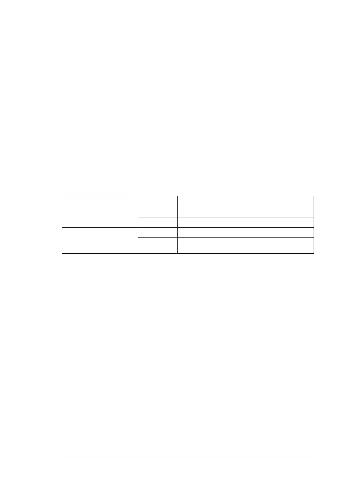
This table describes LEDs of the drive.
* The LEDs are not visible in frame sizes R2 to R6.
Where LED When the LED is lit
RMIO board * Red Drive in fault state
Green The power supply on the board is OK.
Control panel mounting
platform (with type code
selection +0J400 only)
Red Drive in fault state
Green The main +24 V DC power supply for the control panel
and the RMIO board is OK.

 Loading...


