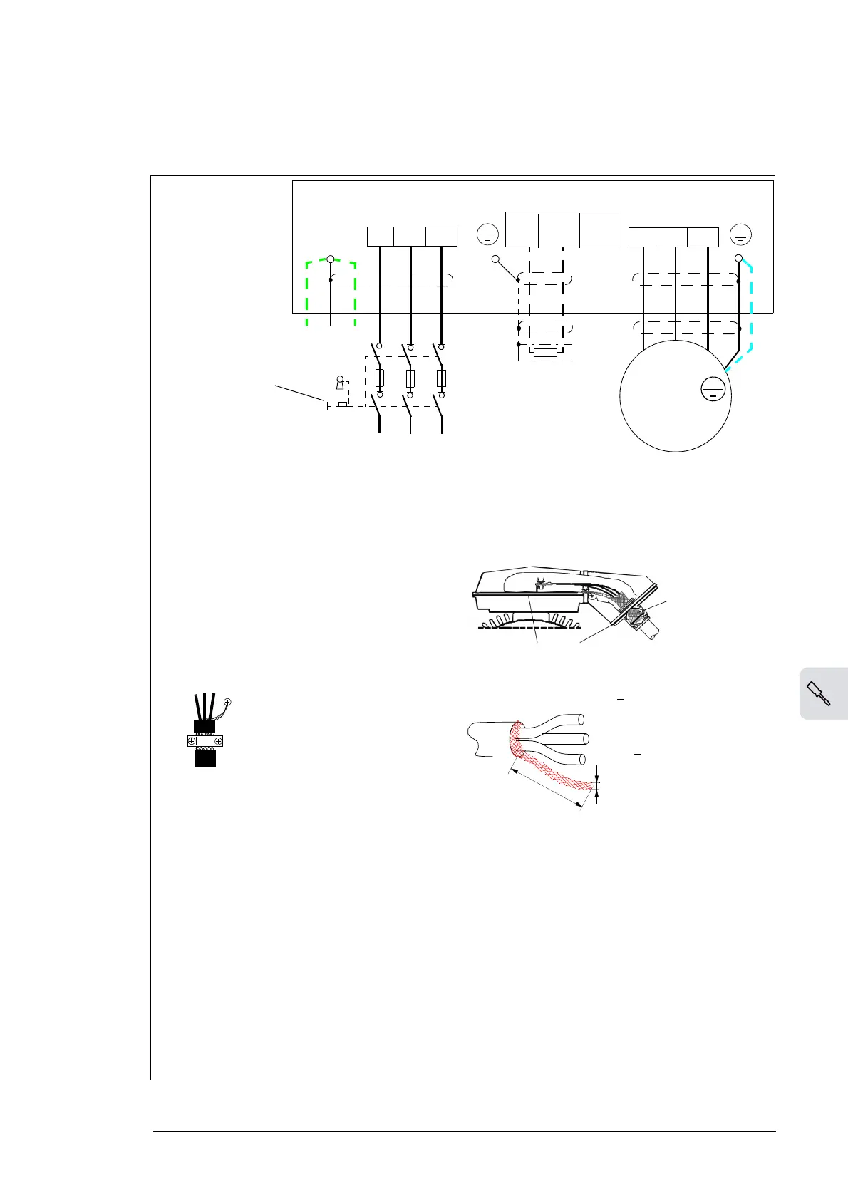
INPUT
OUTPUT
U1
V1
W1
3 ~
Motor
U1
V1 W1
1)
U2
V2 W2
UDC+
R+
UDC
-
R-
L1 L2 L3
(PE) (PE)PE
2)
5)
4)
4)
3)
Drive
PE
For alternatives, see
Disconnecting device
(page 43).
External brake
resistor
Grounding of the motor cable shield at the motor end
For minimum radio frequency interference:
• ground the cable shield 360 degrees at the lead-
through of the motor terminal box
• or ground the cable by twisting the shield as
follows: flattened width >
1/5 · length.
1), 2)
If shielded cable is used (not required but
recommended), use a separate PE cable (1)
or a cable with a grounding conductor (2) if
the conductivity of the input cable shield is
< 50% of the conductivity of the phase
conductor.
Ground the other end of the input cable shield
or PE conductor at the distribution board.
3) 360-degree grounding recommended if
shielded cable
4) 360-degree grounding required
5) Use a separate grounding cable if the
conductivity of the cable shield is < 50% of
the conductivity of the phase conductor
and there is no symmetrically constructed
grounding conductor in the cable (see
Selecting the power cables
on page 50).
Note:
If there is a symmetrically constructed
grounding conductor in the motor cable in
addition to the conductive shield, connect the
grounding conductor to the grounding
terminal at the drive and motor ends.
Do not use an asymmetrically constructed
motor cable for motors > 30 kW (40 hp).
Connecting its fourth conductor at the motor
end increases bearing currents and causes
wear.

 Loading...


