Introduction to this manual 17
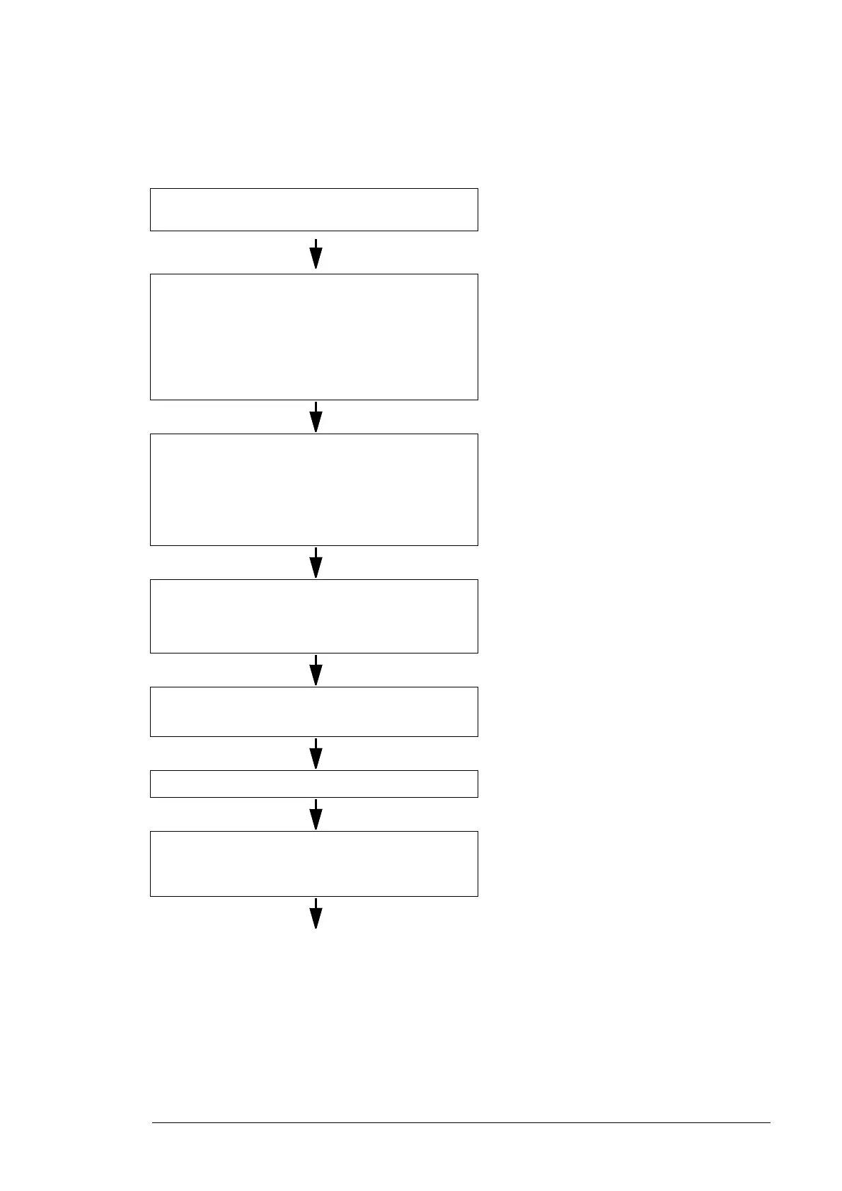
Installation and commissioning flowchart
Task See
Identify the frame size of your drive: R2, R3, R4, R5 or
R6.
IEC data (page 106) or NEMA data (page 119)
Plan the installation.
Check the ambient conditions, ratings, required
cooling air flow, input power connection,
compatibility of the motor, motor connection, and
other technical data.
Select the cables.
Technical data (page 105)
Planning the electrical installation (page 35)
For compliance with the European Union EMC
Directive, see CE marking (page 128)
Option manual (if optional equipment is
included)
Unpack and check the units.
Make sure that all of the necessary option modules
and equipment are present and correct.
Only intact units can be started up.
Unpacking the unit (page 27)
If the converter was not used for more than one
year, the converter DC link capacitors need to
be reformed. See Converter module capacitor
reforming instructions (3BFE64059629
[English]).
If the drive is about to be connected to an IT
(ungrounded) system, make sure that the drive does
not have EMC filtering intended for grounded
systems.
Type code (page 23)
IT (ungrounded) systems (page 60)
Check the installation site. Before installation (page 30)
Technical data (page 105)
Install the drive on a wall or in a cabinet. Mechanical installation (page 27)
Route the cables. Routing the cables (page 58)
For compliance with the European Union EMC
Directive, see CE marking (page 128)

 Loading...


