88 Motor control and I/O board (RMIO)
External control connections (US)
External control cable connections to the RMIO board for the ACS800 Standard
Control Program (Factory Macro US version) are shown below. For external control
connections of other control macros and programs, see the appropriate firmware
manual.
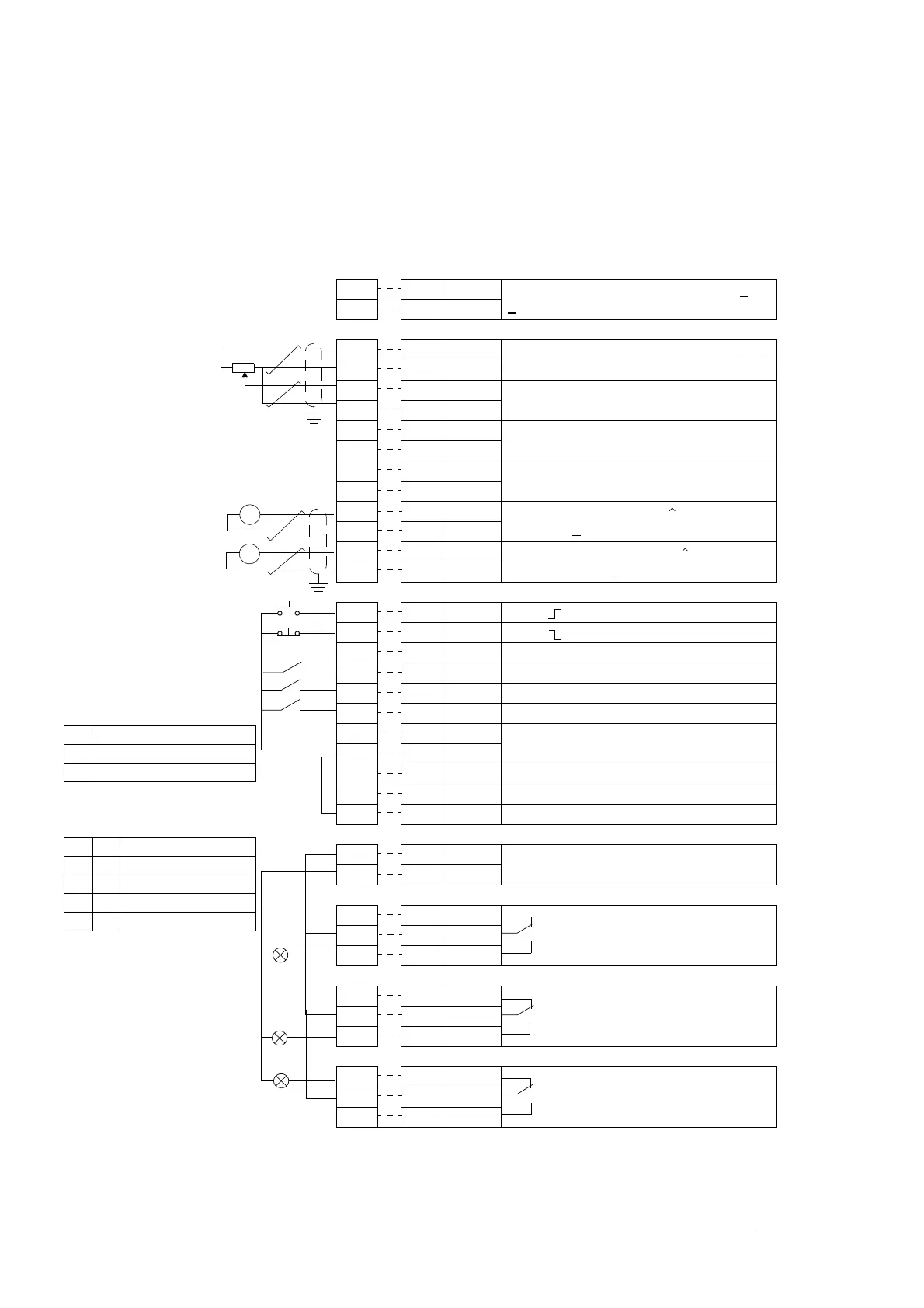
X2* RMIO
X20 X20
1 1 VREF- Reference voltage -10 V DC, 1 kohm <
R
L
< 10 kohm
22 AGND
X21 X21
1 1 VREF+ Reference voltage 10 V DC, 1 kohm <
R
L
<
10 kohm
22AGND
3 3 AI1+ Speed reference 0(2) ... 10 V, R
in
=
200 kohm
44AI1-
5 5 AI2+ By default, not in use. 0(4) ... 20 mA, R
in
=
100 ohm
66AI2-
7 7 AI3+ By default, not in use. 0(4) ... 20 mA, R
in
=
100 ohm
88AI3-
9 9 AO1+ Motor speed 0(4)...20 mA 0...motor nom.
speed, R
L
< 700 ohm
10 10 AO1-
11 11 AO2+ Output current 0(4)...20 mA 0...motor
nom. current, R
L
< 700 ohm
12 12 AO2-
X22 X22
1 1 DI1 Start (
)
22DI2Stop ()
3 3 DI3 Forward/Reverse
1)
4 4 DI4 Acceleration & deceleration select
2)
5 5 DI5 Constant speed select
3)
6 6 DI6 Constant speed select
3)
7 7 +24VD +24 V DC max. 100 mA
8 8 +24VD
9 9 DGND1 Digital ground
10 10 DGND2 Digital ground
11 11 DIIL Start interlock (0 = stop)
4)
X23 X23
1 1 +24V Auxiliary voltage output and input, non-
isolated, 24 V DC 250 mA
5)
22GND
X25 X25
1 1 RO1 Relay output 1: ready
22RO1
33RO1
X26 X26
1 1 RO2 Relay output 2: running
22RO2
33RO2
X27 X27
1 1 RO3 Relay output 3: fault (-1)
22RO3
33RO3
Fault
A
rpm
RMIO
Terminal size:
cables 0.3 to 2.5 mm
2
(22 to 14 AWG)
Tightening torque:
0.2 to 0.4 Nm (0.2 to
0.3 lbf ft)
* optional terminal block in ACS800-
U2 and ACS800-U7
1)
Only effective if par. 10.03 is set
to REQUEST by the user.
2)
0 = open, 1 = closed
3)
See par. group 12 CONSTANT
SPEEDS.
4)
See parameter 21.09 START
INTRL FUNC.
Typically, terminal X22:8 is
connected to X22:11 as
standard.
5)
Total maximum current shared
between this output and option
modules installed on the board.
DI4 Ramp times according to
0 parameters 22.02 and 22.03
1 parameters 22.04 and 22.05
DI5 DI6 Operation
0 0 Set speed through AI1
1 0 Constant speed 1
0 1 Constant speed 2
1 1 Constant speed 3

 Loading...


