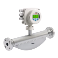
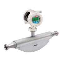
CoriolisMaster FCB330, FCB350, FCH330, FCH350 | CI/FCB300/FCH300-EN Rev. F 13
Chan ge from on e to two c olumns
3 Transport
3.1 Inspection
Check the devices immediately after unpacking for possible
damage that may have occurred from improper transport.
Details of any damage that has occurred in transit must be
recorded on the transport documents.
All claims for damages must be submitted to the shipper
without delay and before installation.
3.2 General remarks
Observe the following when transporting the device to the
measurement site:
— The center of gravity is off center.
— Flange devices may not be lifted by the transmitter
housing or terminal box.
Chan ge from tw o to one c olum n
Chan ge from on e to two c olumns
4 Mounting
4.1 General remarks
The following points must be observed during installation:
— The flow direction must correspond to the marking, if
there is one.
— The maximum torque for all flange connections must be
complied with.
— The meters must be installed without mechanical tension
(torsion, bending).
— Install flange and wafer type devices with coplanar counter
flanges and use only appropriate gaskets.
— Use only gaskets made from a compatible material for the
medium and medium temperature or use only gasket
material compatible with hygienic designs.
— Gaskets must not extend into the flow area since possible
turbulence could influence the device accuracy.
— The pipeline may not exert any unallowable forces or
torques on the device.
— Do not remove the plugs in the cable connectors until you
are ready to install the electrical cable.
— Make sure the gaskets for the housing cover are seated
properly. Carefully gasket the cover. Tighten the cover
fittings.
— A separate transmitter must be installed at a largely
vibration-free location.
— Do not expose the transmitter and sensor to direct
sunlight. Provide appropriate sun protection as necessary.
— When installing the transmitter in a control cabinet, make
sure adequate cooling is provided.
4.2 Flowmeter sensor
The device can be installed at any location in a pipeline under
consideration of the installation conditions.
1. Remove protective plates, if present, to the right and left
of the flowmeter sensor.
2. Position the flowmeter sensor coplanar and centered
between the pipes.
3. Install gaskets between the sealing surfaces.

 Loading...


