24 CI/FCB300/FCH300-EN Rev. F | CoriolisMaster FCB330, FCB350, FCH330, FCH350
Chan ge from tw o to one c olum n
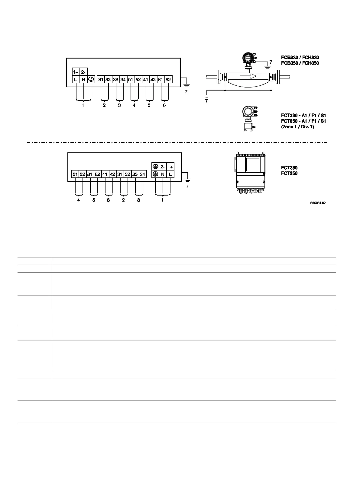
5.6 Terminal connection diagrams
5.6.1 Connection of transmitter models to peripherals
Models FCB330, FCB350, FCH330, FCH350, FCT330, FCT350
Fig. 20
1 Power supply | 2 Current output 1 | 3 Current output 2 | 4 Pulse output | 5 Digital switching output |
6 Digital switching input | 7 Equipotential bonding (PA)
IMPORTANT (NOTE)
When using the device in hazardous areas, note the additional connection data in the chapter titled "Ex relevant specifications"!
Terminal Function
L / N / PE Power supply, 100 … 230 V AC, 50/60 Hz
1+ / 2- / PE Power supply
— 24 V AC, 50/60 Hz
—
24 V DC
31 / 32 Current output 1, active
0/4 … 20 mA , (0 Ω ≤R
≤560 Ω, FCT300-A1/F1:1 0 Ω ≤R
≤300 Ω)
Current output 1, passive
4 … 20 mA (0 Ω ≤R
≤600 Ω), source voltage 12 ≤U
≤ 30 V
33 / 34 Current output 2, passive
4 … 20 mA (0 Ω ≤R
≤600 Ω), source voltage 12 ≤U
≤ 30 V
51 / 52 Pulse output, passive
fmax = 5 kHz, pulse width = 0.1 … 2000 ms, 0.001 ... 1000 pulses/unit
— "Closed": 0 V ≤ U
CEL
≤ 2 V, 2 mA ≤ I
CEL
≤ 220 mA
—
"Open": 16 V ≤ U
≤ 30 V DC, 0 mA ≤ I
≤ 0.2 mA
Pulse output active, U = 16 … 30 V, load ≥ 150 Ω, fmax = 5 kHz
41 / 42 Digital switching output, passive
— "Closed": 0 V ≤ U
CEL
≤ 2 V, 2 mA ≤ I
CEL
≤ 220 mA
— "Open": 16 V ≤ U
≤ 30 V DC, 0 mA ≤ I
≤ 0.2 mA
81 / 82 Digital switching input, passive
— Input "On": 16 V ≤ UKL ≤ 30 V
—
Input "Off": 0 V ≤ UKL ≤ 2 V
- Equipotential bonding "PA"
When the FCT300 transmitter is connected to the FCB3xx / FCH3xx flowmeter sensor, the transmitter must also be connected to "PA".
 Loading...