22 CI/FCB300/FCH300-EN Rev. F | CoriolisMaster FCB330, FCB350, FCH330, FCH350
5.4 Remote mount design
With remote mount design devices, the transmitter is installed
separately and connected to the flowmeter sensor via a signal
cable.
5.4.1 Cable specification
Signal cable
Designation LI2YCY PiMF
5 x 2 x 0.5 mm
2
Shield Pair shielding with continuity wire and copper
Temperature range -30 ... 70 °C (-22 ... 158 °F)
Inductance 0,4 mH/km approx.
5.4.2 Routing the signal cable
Observe the following points when routing cables:
— The signal cable carries a voltage signal of only a few
millivolts and must, therefore, be routed over the shortest
possible distance. The maximum permissible signal cable
length is 10 m (33 ft).
— Avoid routing the cable in the vicinity of electrical
equipment or switching elements that can create stray
fields, switching pulses, and induction. If this is not
possible, route the signal cable inside a metal cable
conduit and connect the cable conduit to operational
ground.
— To shield against magnetic interspersion, the cable
contains outer shielding that is attached to operational
ground.
— Do not run the signal cable over junction boxes or terminal
strips.
5.4.3 Connecting the signal cable
IMPORTANT (NOTE)
Use suitable wire end sleeves when connecting
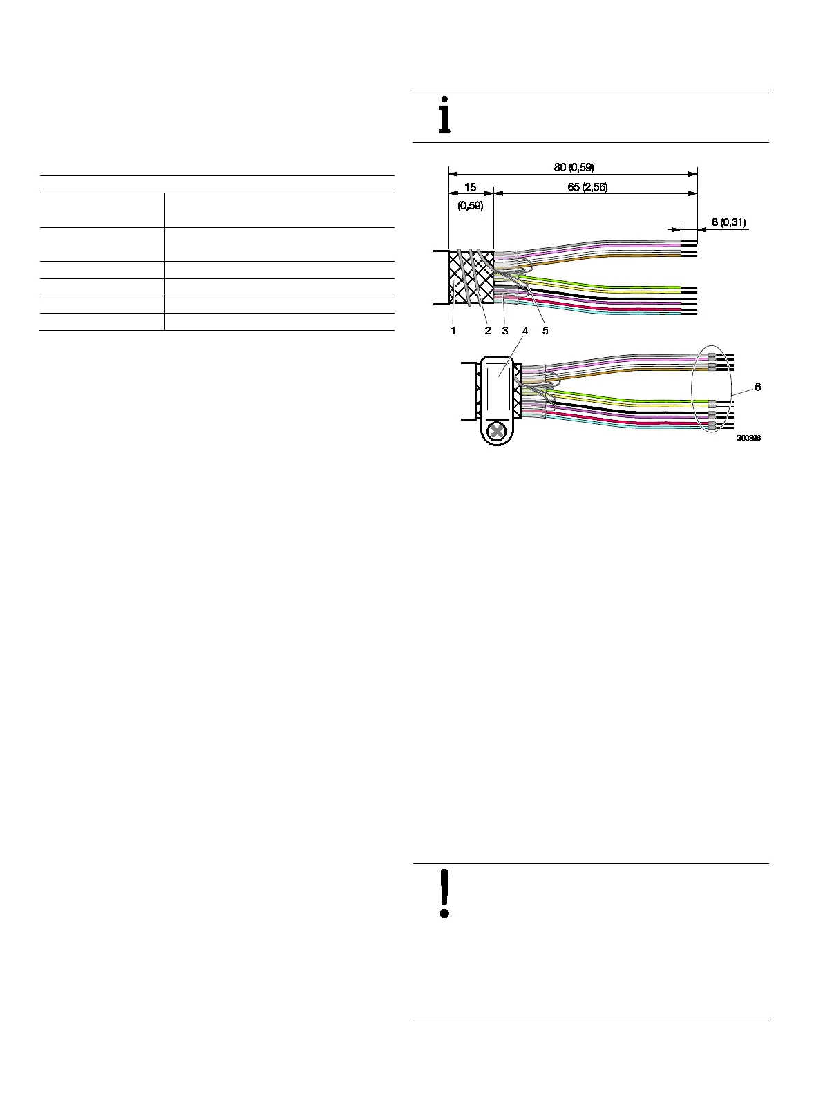
Fig. 18: Signal cable assembly, dimensions in mm (inch)
1 Wire mesh shield | 2 Foil shield continuity wires (twisted) |
3 Foil shield | 4 Grounding clamp | 5 Continuity wire |
6 Wire end sleeves
1. Strip the signal cable as shown.
2. Cut the wire mesh shield to a length of approx. 15 mm
(0.59 inch).
3. Remove the cable core and foil shield from the wire pairs.
4. Strip the wires and attach wire end sleeves.
5. Twist the foil shield continuity wires and wrap them around
the wire mesh shield. When connecting to the devices,
clamp the wire mesh shield and the twisted continuity
wires underneath the grounding clamp.
6. Connect the signal cables to the transmitter and flowmeter
sensor as shown in the connection diagrams.
7. Connect the signal cables for signal inputs and outputs to
the transmitter as shown in the connection diagrams.
Connect the cable shields to the designated grounding
clamp.
8. Connect the power supply cables to the transmitter as
shown in the connection diagrams.
9. Screw all open covers for the transmitter and flowmeter
sensor connection areas back into place.
NOTICE – Potentially adverse effect on
housing ingress protection
If the gasket (o-ring) is seated incorrectly or
damaged, this may have an adverse effect on the
housing ingress protection. Before closing the
housing cover, check the gasket (o-ring) for any
damage and replace if necessary. Check that the
gasket is properly seated when closing the
 Loading...