ABB i-bus
®
KNX
Device technology
FCA/S 1.x.x.1 | 2CDC508134D0202 21
All outputs can be controlled independently.
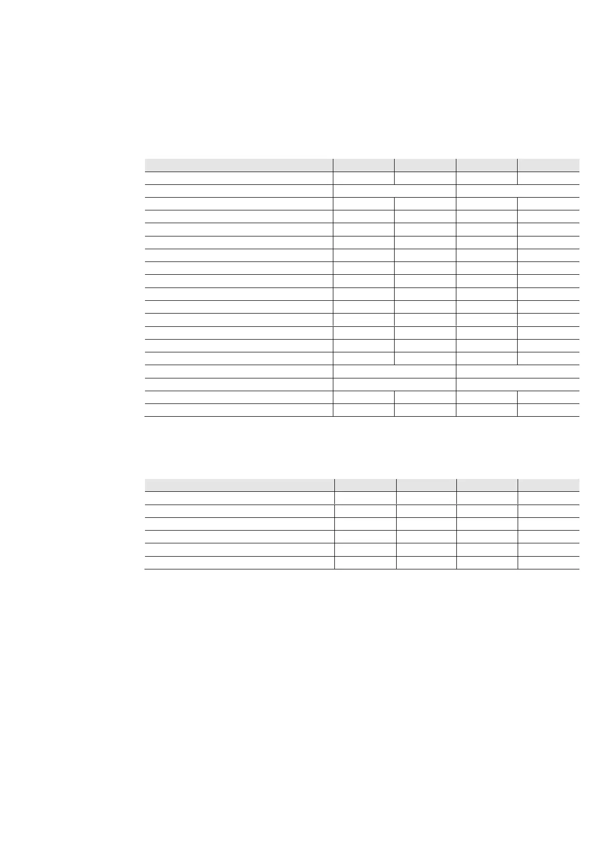
The following table provides an overview of the functions possible with the outputs of the Fan Coil Actuator
and the application:
Valve drives allocated to the Fan Coil unit
- 1 control value/1 valve
- 2 control values/1 valve
- 2 control values/2 valves
Setting facilities for valve drives
- Separate heating/cooling
- Separate heating/cooling
= Function is supported
- = Function is not supported
free = Is available and can be used separately
Normally closed/ Normally open contact
= Function is supported
- = Function is not supported

 Loading...