ABB i-bus
®
KNX
Planning and application
FCA/S 1.x.x.1 | 2CDC508134D0202 245
4.2 Switch output
In this section, the function diagrams and application explanations for the switch outputs are explained.
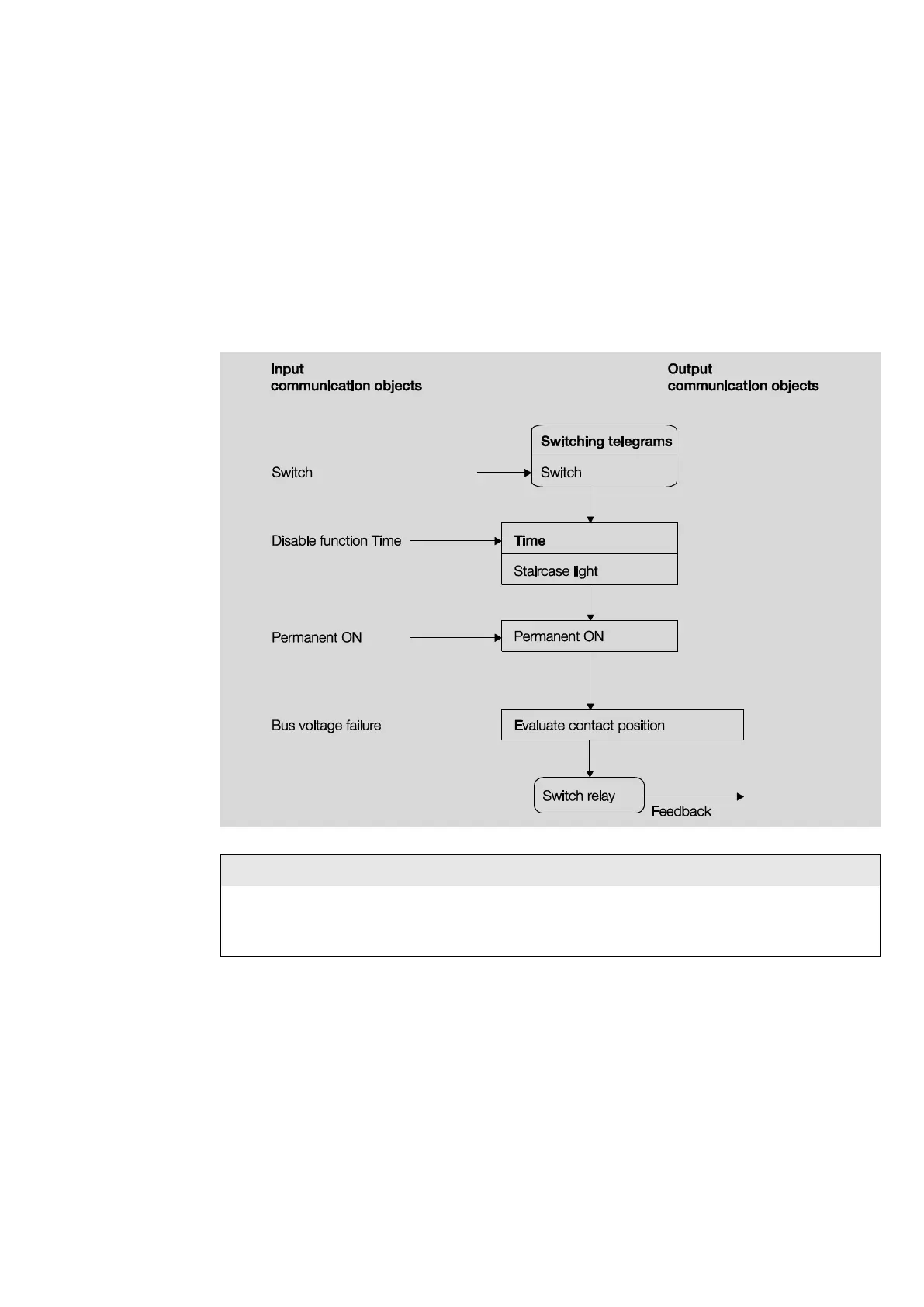
4.2.1 Function diagram
The following illustration indicates the sequence in which the functions are processed. communication
objects which lead to the same box have the same priority and are processed in the sequence in which the
telegrams are received.
When the communication object Switch receives a telegram, the result of that telegram serves as an
input signal for the Time function. If that function is not disabled, a corresponding switch signal is
generated. Subsequently, the switching action is only dependent on the state of the bus voltage. The
relay is switched if a switching action allows it.

 Loading...