ABB i-bus
®
KNX
Device technology
FCA/S 1.x.x.1 | 2CDC508134D0202 35
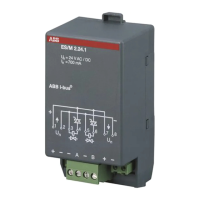
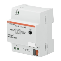
2.3 Fan Coil Actuator FCA/S 1.2.1.2, 0-10V, MDRC
The device is a modular installation
device (MDRC) in Pro M design. It is
intended for installation in distribution
boards on 35 mm mounting rails. The
assignment of the physical addresses as
well as the parameterization is carried out
with ETS.
The device is powered via the ABB
i-bus
®
KNX and requires no additional
auxiliary voltage supply. The device is
ready for operation after connecting the
bus voltage.
*The maximum power consumption of the device
results from the following specifications:
KNX connection
Relay 16 A
Relay 6 A
Analog outputs
0.25 W
1.0 W
0.6 W
0.15 W
Via bus connection terminal
Screw terminal with universal head (PZ 1)
0.2…4 mm² stranded, 2 x (0.2…2.5 mm²)
0.2…6 mm² single core, 2 x (0.2…4 mm²)
Ferrules without/with plastic sleeves
Without: 0.25…2.5 mm²
With: 0.25…4 mm²
0.5…2.5 mm²
Contact pin length min. 10 mm
 Loading...
