4 Quick Installation Guide – MicroFlex e150
Mechanical installation
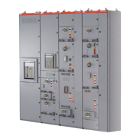
Fasten the drive to the mounting base using screws through the four mounting holes.
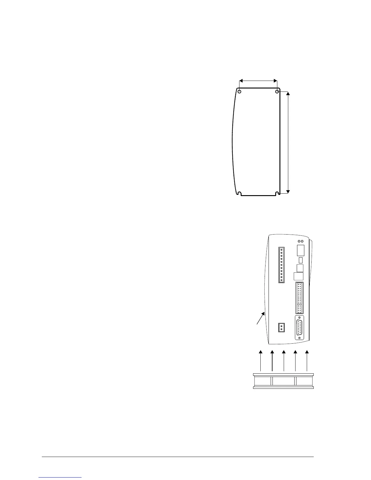
Cooling for 6 A and 9 A models
Effective cooling for the MicroFlex e150 is essential:
• The 3 A model requires no additional cooling.
• The 6 A model requires additional forced air cooling at
1.0 m/s or greater.
• The 9 A model requires additional forced air cooling at
2.5 m/s or greater.
Quoted air velocities are for air originating from below the
MicroFlex e150, passing parallel to the heat sink. With
MicroFlex e150 mounted as specified, quoted air
velocities allow full drive rated current at ambient
temperatures up to 45 °C. Optional fan tray FAN001-024
provides sufficient cooling for all models.
63.5 mm

 Loading...