Quick Installation Guide – MicroFlex e150 7
24 V DC control supply and filter
MicroFlex e150 requires a 24 V DC (20-30 V DC) 1 A supply to power
the control electronics.
Connect the control supply at connector X2.
A fused DC supply should be provided for the MicroFlex e150. If other
devices are to be powered from the same 24 V supply, a filter (catalog
number FI0014A00) should be installed to isolate the MicroFlex e150
from the rest of the system. Alternatively, a ferrite sleeve may be
attached to the supply cable near connector X2.
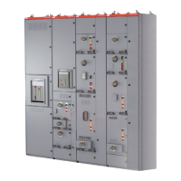
Safe Torque Off (STO) inputs
24 V DC (12-30 V DC) must be applied to both STO inputs
to allow the drive to operate. SREF is common to both
inputs.
Digital I/O
24 V DC (12-30 V DC) general purpose digital inputs and
outputs.
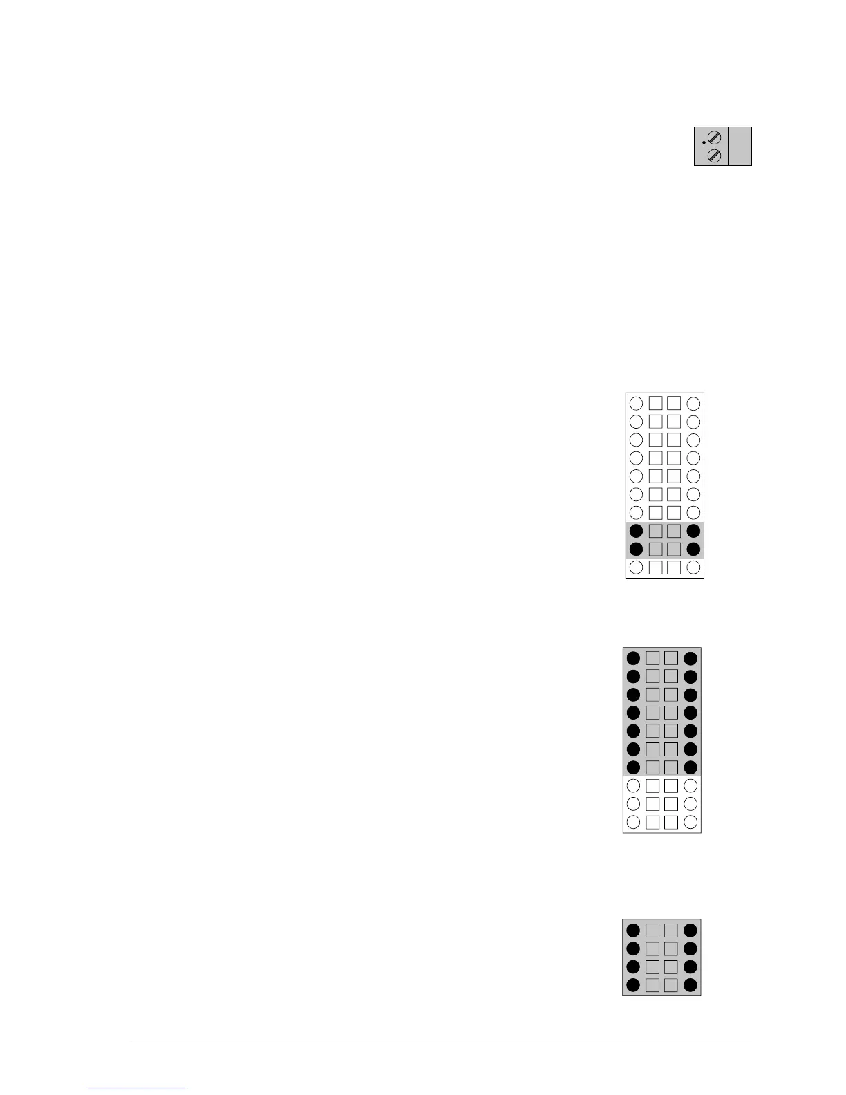
Analog I/O
An analog input can be used to receive a ±10 V demand
signal from a motion controller.
The ±10 V analog output can be used to control external
devices.
Status+
DOUT2+DOUT2-
Status-
DOUT1+DOUT1-
DIN2+DIN2-
DIN3+DIN3-
DIN1+DIN1-
DIN0+DIN0-
X4
AIN1-
AIN0-AIN0+
AIN1+
ShieldShield
AGNDAOUT0

 Loading...