3.9.2 Functions
CONDITION MONITORING
AND SUPERVISION
OR
AND
FEEDER PROTECTION AND CONTROL RELAY STANDARD
CONFIGURATION
PROTECTION
LOCAL HMI
R
L
ClearESC
I
O
Configuration A
System
HMI
Time
Authorization
R
L
ClearESC
I
O
U12 0. 0 kV
P 0.00 kW
Q 0.00 kVAr
IL2 0 A
A
Optional
function
No. of
instances
Alternative
function to be
defined when
ordering
REF615
COMMUNICATION
Protocols:
IEC 61850-8-1
IEC 61850-9-2LE
Modbus
®
IEC 60870-5-103
DNP3
Interfaces:
Ethernet: TX (RJ45), FX (LC)
Serial: Serial glass fiber (ST),
RS-485, RS-232
Redundant protocols:
HSR
PRP
RSTP
G
ALSO AVAILABLE
- Disturbance and fault
- High-Speed Output module (optional)
- Local/Remote push button on LHMI
- Self-supervision
-
Time synchronization: IEEE 1588 v2,
SNTP, IRIG-B
MEASUREMENT
- I, U, Io, Uo, P, Q, E, pf, f
- Limit value supervision
- Load profile record
- Symmetrical components
Analog interface types
1)
Current sensor 3
Voltage sensor 3
Current transformer 1
1)
Combi sensor inputs with conventional
Io input
CONTROL AND INDICATION
1)
Object Ctrl
2)
Ind
3)
CB
DC
ES
1)
Check availability of binary inputs/outputs
from technical documentation
2)
Control and indication function for
primary object
3)
Status indication function for
primary object
1 -
2 3
1 2
I2>
46
I2/I1>
46PD
3Ith>F
49F
3I>>>
50P/51P
ARC
50L/50NL
Master Trip
Lockout relay
94/86
Uo>
59G
Io>>
51N-2
3I>>→
67-2
3I>/Io>BF
51BF/51NBF
3I2f>
68
MCS 3I
MCS 3I
FUSEF
60
CBCM
CBCM
MAP
MAP
SYNC
25
U
L1
U
L2
U
L3
3I
Io
Uo
Io
3I
Io
U
L1
U
L2
U
L3
3×
IEC 61850-9-2LE
SOTF
SOTF
U
L1
U
L2
U
L3
U
L1
Master Trip
Lockout relay
94/86
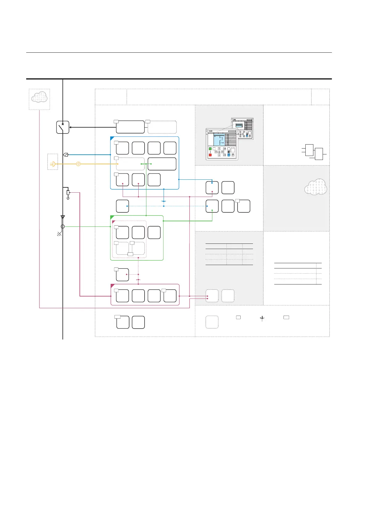
GUID-3524788E-FDB0-4425-9949-C5CBD1301E75 V2 EN
Figure 278: Functionality overview for standard configuration G
3.9.2.1 Default I/O connections
Connector pins for each input and output are presented in the IED physical
connections section.
Section 3 1MRS756378 S
REF615 standard configurations
198 REF615
Application Manual

 Loading...


