manual and auto modes. The relay’s LHMI works as the local
operator interface for controlling the autosynchronizing
sequence. An external injection device (REK 510) enables the
generator’s excitation circuit supervision against earth faults.
Best match for current and voltage measurement needs can be
managed by selecting both AIM1 and AIM2 cards for the relay.
This combination offers 11 current and 9 voltage channels to be
freely allocated to the functionalities in the relay. The
generator’s stator winding temperatures are monitored using
RTD sensors.
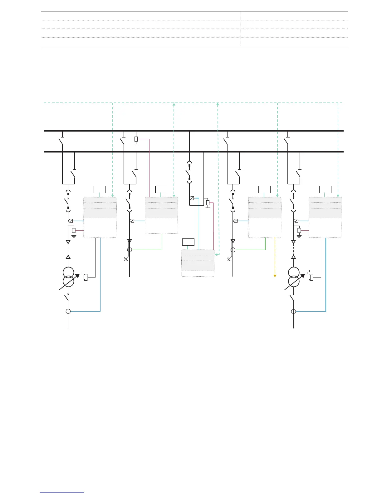
GUID-4205F769-320E-42B1-8206-1F266F73D4FC V1 EN
Figure 14. Digital switchgear application
REX640
is perfectly aligned with the needs of digital switchgear.
Sensors are used for the local phase current and voltage
measurements, apart from the high-voltage side current
measurement used for power transformer protection, which is
carried out by conventional current transformers. For the
outgoing cable feeders, the earth-fault protection uses core
balance current transformers. The Bus A voltage is measured
by the relay in panel +J2, whereas the Bus B voltage is
measured by the relay in panel +J3. Both relays send the
measured bus voltages to the Ethernet bus as sampled
measured values (SMV) according to IEC 61850-9-2 LE.
Depending on the type of the feeder, it receives either one or
two SMV streams. The feeders receiving two SMV streams
automatically switch between the streams based on the
position of the busbar disconnectors. All interlocking signals
between the panels use binary GOOSE messaging according to
IEC 61850-8-1. The incoming power transformer feeders
measure also the cable side voltages to enable automatic
voltage regulation (tap changer control) and synchronizing
check functionality for circuit breaker closing.
1MRS759144 A

 Loading...


