16 TTH300 HEAD-MOUNT TEMPERATURE TRANSMITTER | OI/TTH300-EN REV. E
… 4 Design and function
… Input functionality
If drift monitoring is used for the same types of sensor
(2 × Pt100 or 2 × thermocouple), the mean value calculated from
the two sensors is mapped to the transmitter output signal as a
process variable in redundancy mode.
If a thermocouple is used for Pt100 drift monitoring, the Pt100
sensor (see Resistance thermometers (RTD) / resistors
(potentiometer) on page 22) should be connected to channel 1
and the thermocouple to channel 2.
The measured value from channel 1 (Pt100) is mapped to the
transmitter output as a process variable.
Note
Before configuring the maximum permissible sensor deviation
for drift monitoring, sensor adjustment with respect to the
sensor channel 1 value must be carried out with the help of,
for example. the TTH300 DTM.
Sensor error adjustment in accordance with Callendar-
Van Dusen
Under normal circumstances, the standard Pt100 characteristic
curve is used for resistance thermometer measurement.
However, recent advances in technology now mean that
maximum measuring accuracy can be achieved where necessary
by carrying out individual sensor error adjustment.
Sensor characteristic curves are optimized by using a Pt100
polynomial in accordance with IST-90 / IEC 751, and EN 60150,
and by applying A ,B, C, or Callendar-Van Dusen coefficients.
With the help of the DTM, EDD or FDI package (FIM), these
sensor coefficients (Callendar-Van Dusen) can be adjusted and
stored in the transmitter as a CVDcharacteristic curve. Up to five
different CVDcharacteristic curves can be stored for HART and
PROFIBUS PA, while up to two CVDcharacteristic curves can be
stored for FOUNDATION Fieldbus.
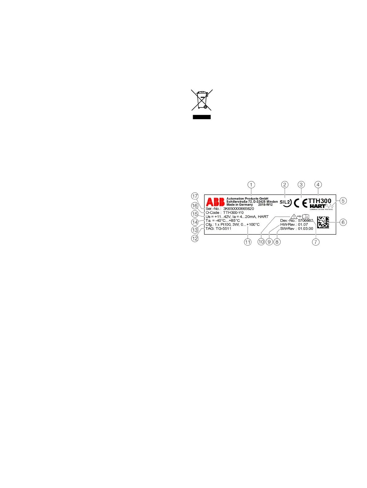
5 Product identification
Name plate
Note
Products that are marked with the adjacent symbol
may not be disposed of as unsorted municipal waste
(domestic waste).
They should be disposed of through separate
collection of electric and electronic devices.
Note
The ambient temperature range
n
provided on the name plate
refers only to the transmitter itself and not to the sensor
element used in the measuring inset.
For devices with PROFIBUS PA or FOUNDATION Fieldbus, the
device-ID is also specified.
1 Manufacturer, manufacturer address, manufacturing year - week
2 Safety integrity level, SIL logo (optional with HART transmitter)
3 CE mark (EU conformity), if not on additional plate
4 Type designation / model
5 Transmitter communications protocol (HART, FF, PA)
6 2D barcode for serial number in accordance with order
7 7-digit serial number of the device electronic unit
8 Software revision
9 Hardware version
0 ‘Follow product documentation’ symbol
k l m
HART transmitter:
k Set measuring range of the transmitter
l Measuring point tag (TAG) in accordance with order (optional)
m Set sensor type and circuit type
l m Transmitter FOUNDATION Fieldbus or PROFIBUS PA:
l Measuring point tag (TAG) in accordance with order (optional)
m DEVICE_ID or Ident_Number
n Ambient temperature range, on additional plate for Ex versions
o Transmitter specification (supply voltage range, output current range,
communications protocol)
p Coding of the type of protection of the device (in accordance with
ordering information)
q Serial number of the device (serial number in accordance with order)
Figure 7: HART name plate (example)

 Loading...


