34 TTH300 HEAD-MOUNT TEMPERATURE TRANSMITTER | OI/TTH300-EN REV. E
… 11 Operation
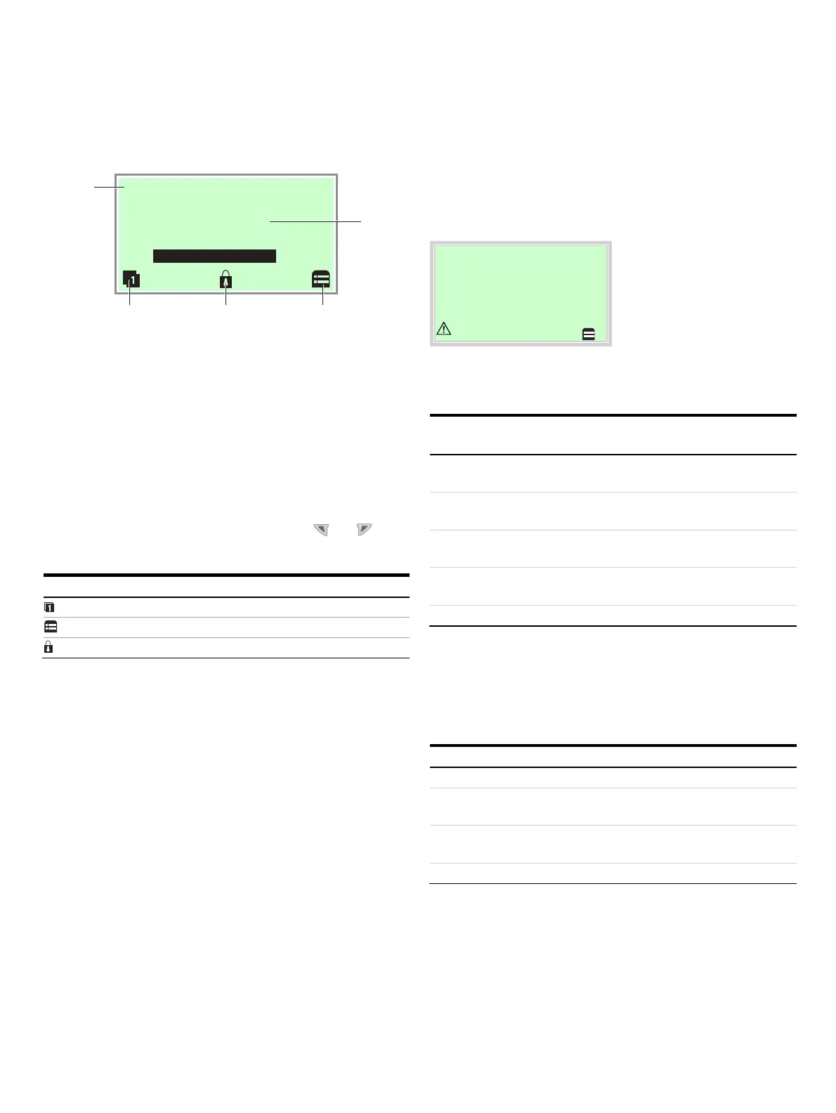
Process display
A11124
-
°C
PV 100%
25.7
1
433
2
1 Measuring point tagging (Device
TAG)
2 Current process values
3 ‘Button function’ symbol
4 ‘Parameterization protected’
symbol
Figure 25: Process display (example)
The process display appears on the LCD display when the device
is powered on. It shows information about the device and
current process values.
The way in which the current process values are shown can be
adjusted on the configuration level.
The symbols at the bottom of the process display are used to
indicate the functions of the operating buttons and , in
addition to other information.
Symbol Description
Call up information level.
Call up configuration level.
The device is protected against changes in the parametrization.
Error messages on the HART® LCD display
If the event of an error, a message consisting of a symbol or
letter (device status) and a number (DIAG NO.) will appear at the
bottom of the process display.
Process dis
la
Application F72
The diagnostic messages are divided into the following groups
in accordance with the NAMUR classification scheme:
Symbol -
Letter
Description
I OK or Information Device is functioning or information is
available
C Check Function Device is undergoing maintenance (for
example simulation)
S Off Specification Device or measuring point is being
operated outside of the specifications
M Maintenance
Required
Request service to prevent the measuring
point from failing
F Failure Error; measuring point has failed
The error can then be read in plain-text format on the ‘Diagnosis’
information level.
Additionally, the diagnostic messages are divided into the
following areas:
Range Description
Electronics Diagnosis for device hardware.
Sensor Diagnosis for sensor elements and connection
lines.
Installation /
Configuration
Diagnosis for communication interface and
parameterization / configuration
Operating conditions Diagnosis for ambient and process conditions.
Note
For a detailed description of the errors and notices on
troubleshooting, see Diagnosis / error messages on page 54.

 Loading...


