TTH300 HEAD-MOUNT TEMPERATURE TRANSMITTER | OI/TTH300-EN REV. E 31
Basic Setup
Note
Transmitter communication and configuration via HART,
PROFIBUS PA, and FOUNDATION Fieldbus H1 are described in
separate documentation (‘Interface description’).
The following configuration types are available for the
transmitter:
• With DTM:
Configuration can be performed within an FDT frame
application that is approved for use with the DTM.
• With EDD:
Configuration can be performed within an EDD frame
application that is approved for use with the EDD.
• With FDI-Package (FIM):
Configuration is possible within an FDI frame applications
(Field Information Manager / FIM) for which the FDI
packages are released.
• With LCD indicator Type A with operating buttons
Commissioning via the LCD indicator does not require any
tools to be connected to the device and is therefore the
simplest way of configuring the TTH300.
The general operation and menus of the LCD indicator are
described in Menu navigation on page 32.
Note
Unlike configuration using the DTM, EDD or FDI-Package (FIM)
the functionality of the transmitter can only be changed to a
limited extent with the LCD indicator.
11 Operation
Safety instructions
If there is a chance that safe operation is no longer possible,
take the device out of operation and secure it against
unintended startup.
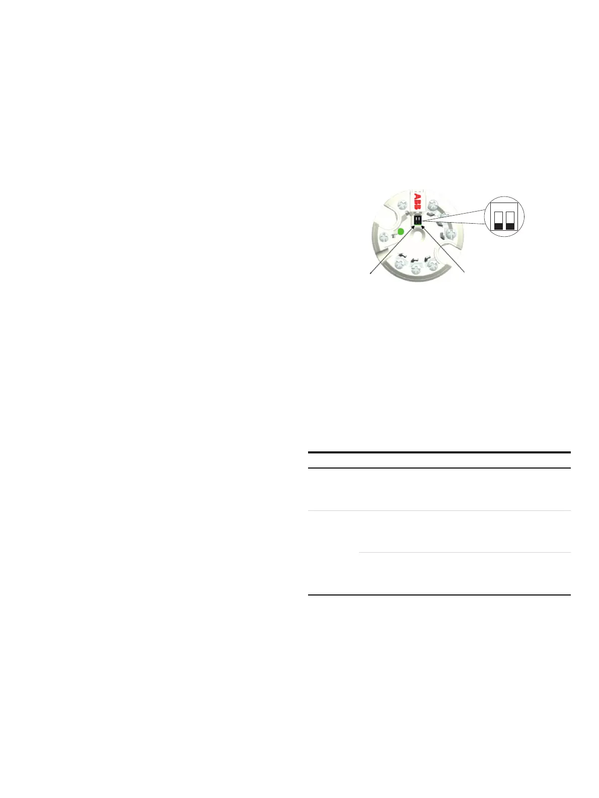
Hardware settings
A10256
12
On
12
a DIP switch 1 b DIP switch 2
Figure 23: DIP switch on the transmitter
The transmitter has two DIP switches that can be accessed via a
hinged cover.
• Switch 1 activates the hardware write protection.
• Switch 2 supports the FOUNDATION Fieldbus
requirement for a hardware enable for simulation in
accordance with ITK.
For transmitters that support HART 7, switch 2 allows the
desired HART version to be set (HART 5 or HART 7).
DIP switch Function
1 Local write protection
Off: Local write protection deactivated
On: Local write protection activated
2 Enabling the simulation (only with FOUNDATION Fieldbus)
Off: Simulation blocked
On: Simulation enabled
Selecting the HART version (only with HART protocol)
Off: HART 5
On: HART 7
Note
• Factory settings: Both switches ‘OFF’. Local write protection
deactivated and HART 5, unless explicitly ordered HART 7
(HART version) or simulation locked (FOUNDATION Fieldbus).
• With PROFIBUS PA devices, Switch 2 must always be in the
‘OFF’ position.

 Loading...


