- 83 -
000692CG
5 - Installation
Remote control connection
The connection and disconnection of the inverter to and from the grid can
be controlled through an external control.
The function must be enabled in the specic section of web user interface
(see the specic chapter) or through the display and the keyboard in the
specic menu (see the side picture). If the remote control function is disa
-
bled, the switching on of the inverter is dictated by the presence of the nor-
mal parameters that allow the inverter to connect to the grid. If the remote
control function is operating, besides being dictated by the presence of the
normal parameters that allow the inverter to connect to the grid, start-up of
the inverter also depends on the state of the terminal R+ compared to the
terminal RTN present on the connector
26
.
When the R+ signal is brought to the same potential as the RTN signal
(that is to say when a short-circuit is created between the two connector
terminals), the inverter is disconnected from the grid.
The remote control OFF condition is shown on the display.
Connections for this command are made between input “R+” and “RTN”.
Since this is a digital input, there are no requirements to be observed
as regards cable cross-section (it only needs to comply with the sizing
requirement for passing cables through the cable glands
20
and the ter-
minal connector
26
). The cable specications are described in the fol-
lowing table:
AWG Operating voltage Operating temperature
22 - 24 ≥300 V -20...+60 °C
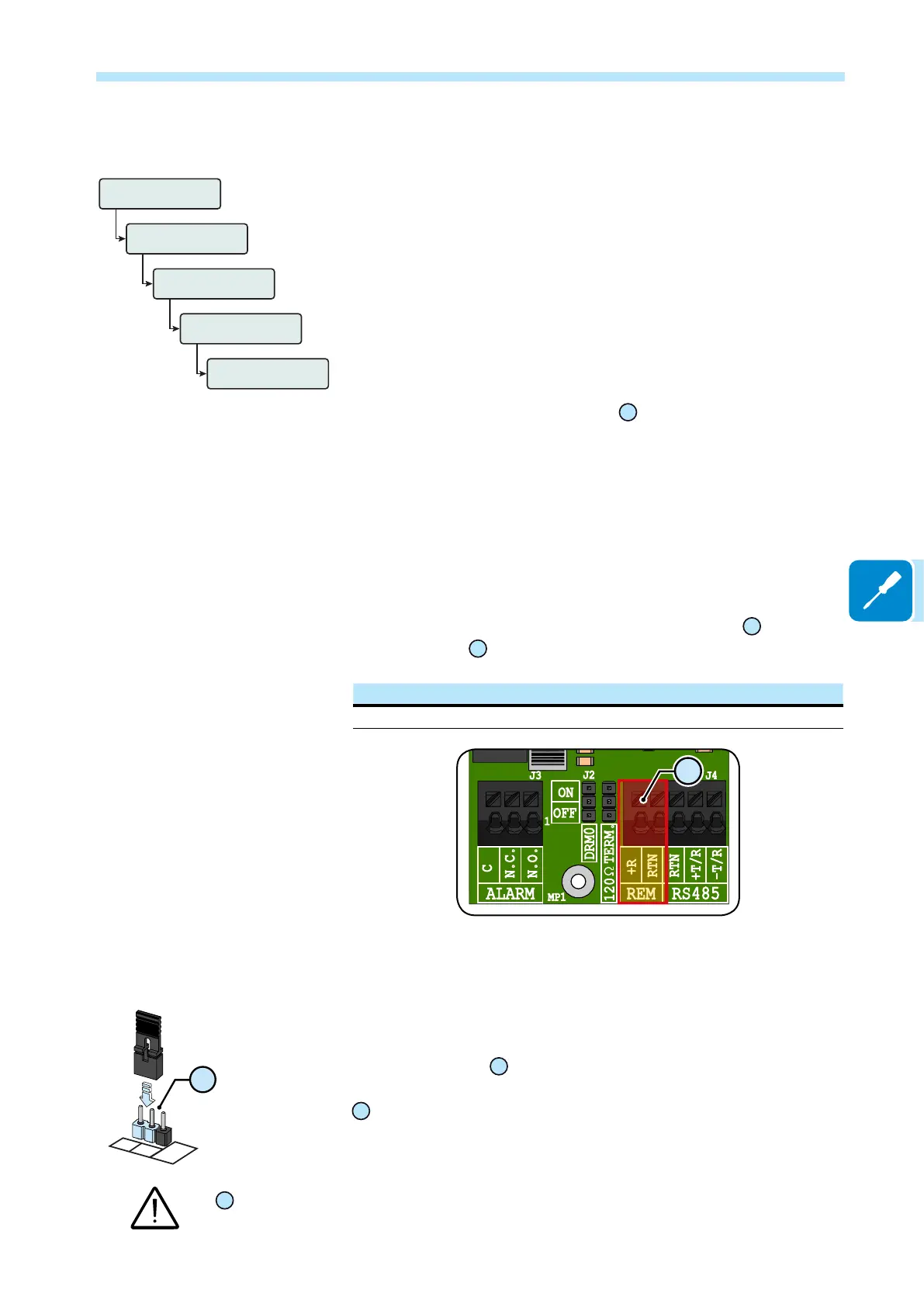
K1
J2
J3
1
J4
MP1
-T/R
RTN
RTN
RS485REM
+T/R
+R
120
TERM.
ON
OFF
DRM0
N.C.
N.O.
ALARM
C
UNO-DM-COM KIT
06
Demand Responce Mode 0 (Request by AS/NZS 4777)
Where requested by the AS/NZS 4777 standard, it’s possible to use the
REM terminal block
26
for the Demand Responce Mode 0 (DRM0) func-
tionality. The function could be activated by placing the provided jumper
23
in “ON” position.
In case of the DRM0 function is activated without the proper wiring of the REM terminal block
26
, the inverter will no longer be able to connect to the grid. For further information regarding
the DRM0 function refer to the AS/NZS 4777 standard.
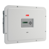
Inverter
Settings
Password
0000
Remote ON/OFF
En/Dis Remote
Enabled
DRM0
ON
OFF
23
 Loading...