Functions
Exterior features of E‐GANG6
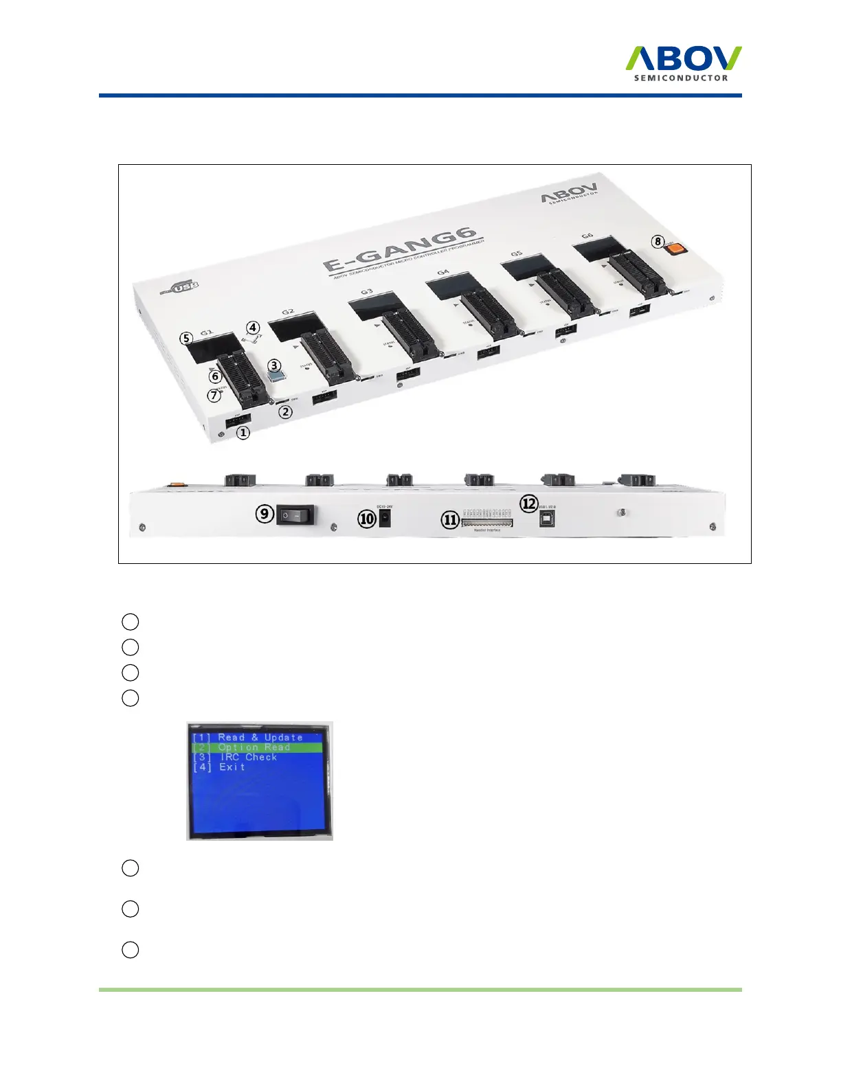
Figure 5: E-GANG6 exterior view for function description
1 10-pin IDC connector for in-system programming (ISP)
2
SWD port for firmware update and development purposes (not for use)
3 Button for programming the target device “G1” only
4 Button for reading the target device
5 LCD screen for information display—device name, checksum data, and options. PASS/FAIL is
shown as a result of programming, accompanied by an error description in case of failure
6
40-pin DIP TEXTOOL socket for gang programming mode—Gang4 has four separate sockets
and Gang6 has six separate sockets
7 LED indicator showing the current status when writing is complete (Red: FAIL / Green: PASS)
E-PGM+ E-GANG4/E-GANG6 E-PGM Serial Page 10 / 33 Version 1.0.0
 Loading...