10-pin connector pin configuration
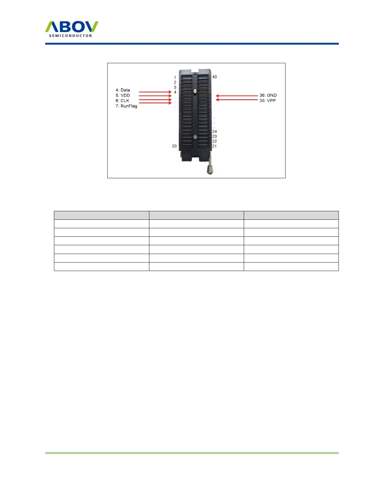
Figure 8: 40-pin DIP TEXTOOL socket and programming pin assignment
Table 2: Pin name and assignment
Pin no.
40-pin DIP socket
ISP connector
VDD
5
2
GND
36
4
CLOCK
6 6
DATA
4
8
VPP/Reset
35 10
RunFlag/Boot
7
5
Pin no.
40-pin DIP socket
ISP connector
VDD
5
2
GND
36
4
CLOCK
6 6
DATA
4
8
VPP/Reset
35 10
RunFlag/Boot
7
5
2.5 10‐pin connector pin conguraon
A 10-pin IDC type connector is required for on-board programming with E-PGM+, E-GANG4/6 and
E-PGM Serial. The target board and 10-pin connector must be connected correctly for programming.
An improper connection will pop up the Device–ID Fail message on the LCD screen.
Version 1.0.0 Page 13 / 33 E-PGM+ E-GANG4/E-GANG6 E-PGM Serial
 Loading...