40-pin DIP TEXTOOL socket pin configuration
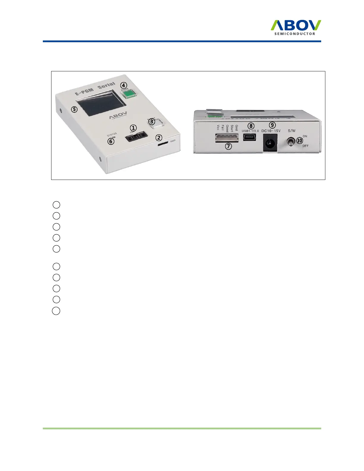
Exterior features of E‐PGM Serial
Figure 7: E-PGM Serial top and side views for function description
1 10-pin IDC connector for in-system programming (ISP)
2
SWD port for firmware update and development purposes (not for use)
3 Button for programming the target device
4 Button for reading the target device
5 LCD screen for information display—device name, checksum data, and options. PASS/FAIL is
shown as a result of programming, accompanied by an error description in case of failure
6 LED indicator showing the current status when writing is complete (Red: FAIL / Green: PASS)
7 5-pin Molex 5264 connector for the interface with handler equipment
8
USB mini-B connector to a PC
9 Power adaptor connector for the 15V/1A external power
10
System power switch
2.4 40‐pin DIP TEXTOOL socket pin conguraon
E-PGM+ and E-GANG4/6 (not E-PGM Serial) use specific sockets to program one or a gang of devices.
The user should place the appropriate socket and adapter on the 40-pin DIP TEXTOOL socket before
conducting programming. ABOV Semiconductor provides all sockets and adaptors compatible with E-
PGM+ and E-GANG4/6. Please refer to the Socket and Adaptor Selection Guide for your target device.
The following figure and table show the signal assignment of the 40-pin DIP TEXTOOL socket.
E-PGM+ E-GANG4/E-GANG6 E-PGM Serial Page 12 / 33 Version 1.0.0
 Loading...