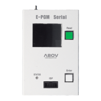
Figure 6 E-PGM serial exterior view . . . . . . . . . . . . . . . . . . . . . . . . . . . . . . . 11
Figure 7 E-PGM Serial top and side views for function description . . . . . . . . . . . . . . . 12
Figure 8 40-pin DIP TEXTOOL socket and programming pin assignment . . . . . . . . . . . 13
Figure 9 10-pin IDC connector pin assignment . . . . . . . . . . . . . . . . . . . . . . . . . 14
Figure 10 An example connection of multiple E-PGM+ units . . . . . . . . . . . . . . . . . . . 31
Figure 11 Internal step-up power selection . . . . . . . . . . . . . . . . . . . . . . . . . . . . 32
Figure 12 Insertion of a 200 ohm resistor in VPP line . . . . . . . . . . . . . . . . . . . . . . . 33
List of Tables
Table 1 Comparison between E-PGM+, E-GANG4/6, and E-PGM Serial . . . . . . . . . . . 7
Table 2 Pin name and assignment . . . . . . . . . . . . . . . . . . . . . . . . . . . . . . . . 13
Table 3 10-pin IDC connector pin configuration for each device group . . . . . . . . . . . . 14
E-PGM+ E-GANG4/E-GANG6 E-PGM Serial Page 4 / 33 Version 1.0.0
 Loading...