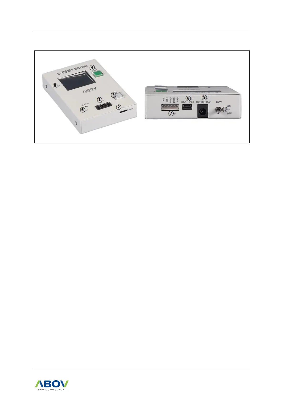
Figure 5. E-PGM Serial Top and Side Views for Function Description
① 10-pin IDC connector for In-System Programming (ISP)
② SWD port for firmware update and development purpose (Do not use, it is not for
customers.)
③ A button for programming the target device
④ A button for reading the target device
⑤ LCD Screen for Information Display:
— Device name, checksum data and options.
— PASS/FAIL is shown as a result of programming, accompanied by error information
in the case of failure.
⑥ LED Indicator with red/green illumination shows the current status when writing is
complete:
— Red for FAIL
— Green for PASS
⑦ 5-pin Molex 5264 connector for the interface with a Handler equipment
⑧ USB mini-B connector to a PC
⑨ Power Adaptor Connector for the 15V/1A external power
⑩ System Power Switch
 Loading...