EasyManuals Logo
Home>Abov>Motherboard>E-PGM+

Abov E-PGM+ User Manual

Abov E-PGM+
47 pages
To Next Page IconTo Next Page
To Previous Page IconTo Previous Page
Page #44 background imageLoading...
Page #44 background image
6. PCB V5.5 SW3 Settings E-PGM+ / E-GANG4/6 / E-PGM Serial User’s Manual
44
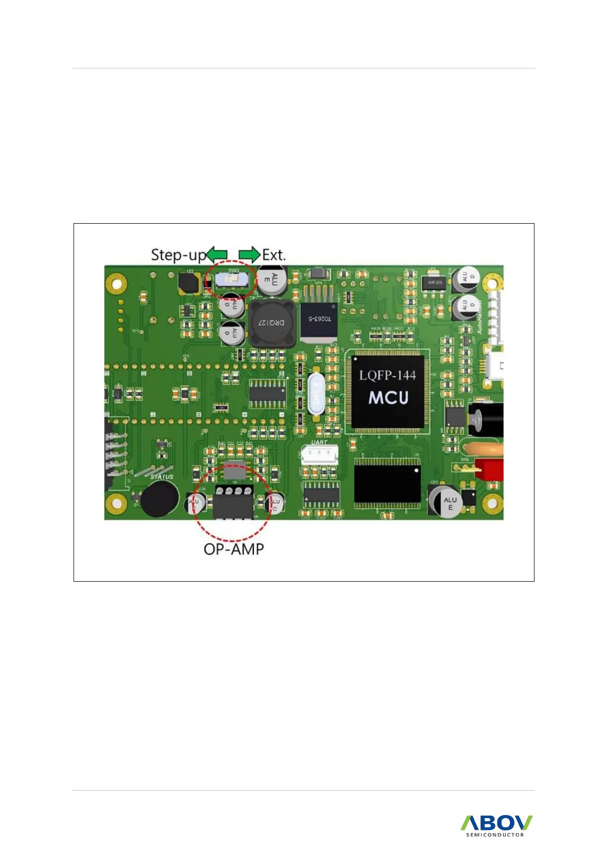
6 PCB V5.5 SW3 Settings
MC97F1104S, MC97F1204S, and MC97F1316S require a higher VPP of 17V when programmed,
and therefore users need to set the SW3 switch in the Step-up position to ensure a maximum VPP
level of 19V.
When programming any other devices, on the other hand, users must set the switch to be in the
Ext position to limit the maximum VPP level to 15V. If the switch SW3 is set in the Step-up position,
the OP-AMP can be damaged when the VDD and ground are shorted during on-board
programming.
Figure 50. Internal Step-up Power Selection

Table of Contents

Questions and Answers:

Question and Answer IconNeed help?

Do you have a question about the Abov E-PGM+ and is the answer not in the manual?

Abov E-PGM+ Specifications

General IconGeneral
BrandAbov
ModelE-PGM+
CategoryMotherboard
LanguageEnglish

Related product manuals