EasyManuals Logo
Home>Abov>Motherboard>E-PGM+

Abov E-PGM+ User Manual

Abov E-PGM+
47 pages
To Next Page IconTo Next Page
To Previous Page IconTo Previous Page
Page #41 background imageLoading...
Page #41 background image
E-PGM+ / E-GANG4/6 / E-PGM Serial User’s Manual 4. Connection of Handler
41
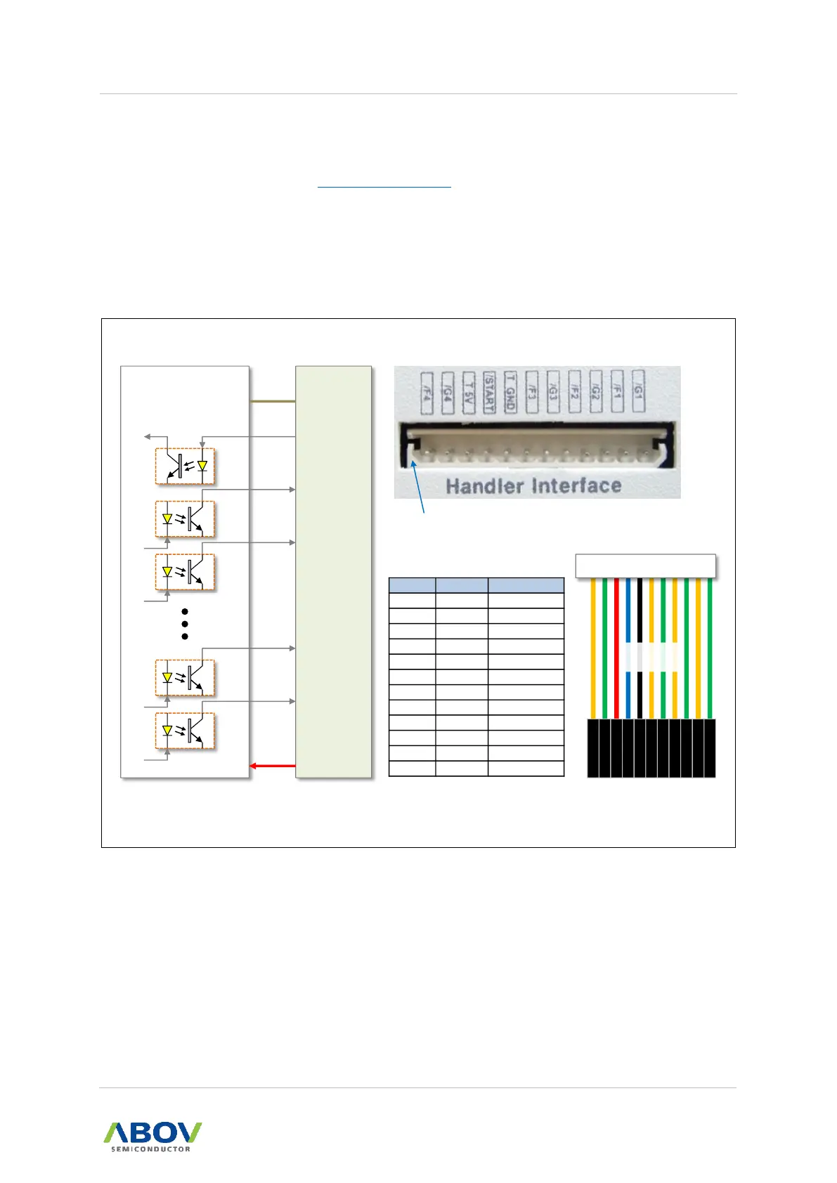
4.2 E-GANG4 Handler Connections
The software and firmware for the E-PGM+, E-GANG4/6 and E-PGM Serial are available for
download from ABOV’s website (www.abovsemi.com).
Built-in internal isolator circuit
Used the handler power +5V or +3.3V (Used target power)
START: Input pin, active low
GOOD/FAIL: Output pin, active low, indicate signals
#1 Marking
1 2 3 4 5 6 7 8 9 10 11 12
Pin No.
Marking
Name
1 Blank Not used
2 /F4 FAIL4
3 /G4 GOOD4
4 T_5V
Target Power
5 /START START
6 T_GND
Target GND
7 /F3 FAIL3
8 /G3 GOOD3
9 /F2 FAIL2
10 /G2 GOOD2
11 /F1 FAIL1
12 /G1 GOOD1
E-GANG4
Programmer
/START
/F1
/G1
T_5V
T_GND
Handler
6
5
11
12
4
Common
+5V
(+3.3V)
/F4
/G4
2
3
FAIL1
GOOD1
FAIL4
GOOD4
VCC
GND
FAIL4
GOOD4
T_5V
START
T_GND
FAIL3
GOOD3
FAIL2
GOOD2
FAIL1
GOOD1
L R
TOP
Handler Interface Cable
(Active Low)
300mm
Length
START
Figure 47. E-GANG4 Handler Connections

Table of Contents

Questions and Answers:

Question and Answer IconNeed help?

Do you have a question about the Abov E-PGM+ and is the answer not in the manual?

Abov E-PGM+ Specifications

General IconGeneral
BrandAbov
ModelE-PGM+
CategoryMotherboard
LanguageEnglish

Related product manuals