EasyManuals Logo
Home>Abov>Motherboard>E-PGM+

Abov E-PGM+ User Manual

Abov E-PGM+
47 pages
To Next Page IconTo Next Page
To Previous Page IconTo Previous Page
Page #16 background imageLoading...
Page #16 background image
2. Hardware E-PGM+ / E-GANG4/6 / E-PGM Serial User’s Manual
16
2.3.2 10-pin Connector
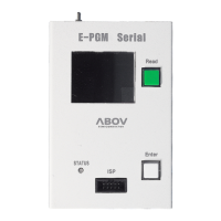
A 10-pin IDC type connector is required for On-board programming with E-PGM+, E-GANG4/6
and E-PGM Serial. The target board and 10-pin connector must be connected correctly for
programming. If the connection is incorrect, the “Device–ID Fail.” message is displayed on the
LCD screen.
Figure 10. Programming Pin Assignment for 10-pin Connector
Table 4. Connection Table for 10-pin IDC Connector
Pin No.
Supported Signals
AC33M6128/8128,
AC33M3064/4064
MC80F7708
UART ISP
32-bit SWD
1
MCU UART-RX
MCU UART-RX
MCU UART-RX
N/A
2
VDD
VDD
VDD
VDD
3
MCU UART-TX
MCU UART-TX
MCU UART-TX
N/A
4
GND
GND
GND
GND
5
Run Flag or Boot
Pin or ACK
Boot Pin
ACK
N/A
6
DSCL, CLK (Clock)
N/A
N/A
SWD-CLK
7
GND
N/A
N/A
N/A
8
DSDA, Data
N/A
N/A
SWD-DATA
9
N/A
N/A
N/A
N/A
10
VPP or Reset Pin
RESET
VPP
RESET

Table of Contents

Questions and Answers:

Question and Answer IconNeed help?

Do you have a question about the Abov E-PGM+ and is the answer not in the manual?

Abov E-PGM+ Specifications

General IconGeneral
BrandAbov
ModelE-PGM+
CategoryMotherboard
LanguageEnglish

Related product manuals