21
Thermostat
Thermostat setting Thermostat status Priority Control panel Main unit
Without O / / /
Air conditioning
Heating / Heating On for heating
Cooling / Cooling On for cooling
O / Last operation mode O
Air+ hot water
Heating
ACS DHW + Heating First water heating and then heating
Heat/Cool Heating + DHW On for heating; water heated by the water heater electric heater
Cooling
ACS Hot water + cooling First water heating and then cooling
/ Cooling + hot water On for cooling; water heated by the water heater electric heater
O / ACS On for water heating
Air+ hot water2
Heating / Heating On for heating
Cooling / Cooling On for cooling
Hot domestic water / ACS On for water heating
Heating + DHW
ACS DHW + Heating First water heating and then heating
Heat/Cool Heating + DHW On for heating; water heated by the water heater electric heater
Cooling + hot water
ACS Hot water + cooling First water heating and then cooling
Heat/Cool Cooling + hot water On for cooling; water heated by the water heater electric heater
O / Last operation mode O
6.7 SETTING AN ADDITIONAL HEAT SOURCE OTHER
THERMAL
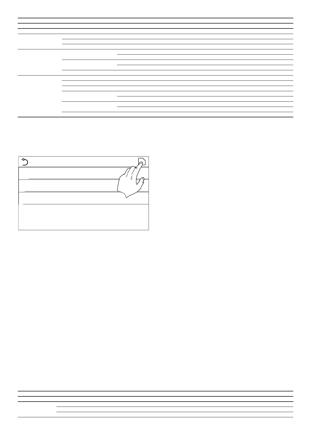
At the commissioning parameter setting page, by touching “Other thermal”, the
control panel will access to the corresponding setting page.
Other thermal
Other thermal: With
T Other switch on: -20°C
Logic: 1
After accessing the "Additional heat source" function, you can activate or deactivate
the substitute heat source and set the outdoor temperature threshold below which
it will be activated in place of the heat pump; you can also dene the logic for man-
aging the substitution. The available logic items are:
Logic 1
With this logic, the 2-way valve is managed on the basis of the control panel set-
tings; the operating modes will therefore be managed when the temperature
measured by the outside air probe is lower than the "Additional heat source temp."
parameter:
— Heating: the unit (and its circulator) will not be active, the 3-way valve will be
blocked on the system side, and the additional heat source will be activated;
once the set value has been reached, the additional heat source will be deacti-
vated and the unit will activate its circulator.
— DHW: the unit (and its circulator) will not be active, the 3-way valve will be
blocked on the DHW side, and the additional heat source will be activated.
— Heating + DHW: the unit (and its circulator) will not be active, the 3-way valve
will be blocked on the system side, and the additional heat source will be acti-
vated; once the set value has been reached, the additional heat source will be
deactivated and the unit will activate its circulator; the DHW side will be man-
aged using only the electric heaters of the compatible Aermec accessory tank.
Logic 2
With this logic, the 2-way valve is managed on the basis of the control panel set-
tings; the operating modes will therefore be managed when the temperature
measured by the outside air probe is lower than the "Additional heat source temp."
parameter:
— Heating: the unit (and its circulator) will not be active, the 3-way valve will be
blocked on the system side, and the additional heat source will be activated;
once the set value has been reached, the additional heat source will be deacti-
vated and the unit will activate its circulator.
— DHW: the unit (and its circulator) will not be active, the 3-way valve will be
blocked on the DHW side, and the additional heat source will be activated.
— Heating + DHW:
1. If the priority is "Heating" (paragraph "4.4Heating + DHWp. 10"), the unit
(and its circulator) will not be active, the 3-way valve will be blocked on the sys-
tem side, and the additional heat source will be activated; once the set value
has been reached, the additional heat source will be deactivated and the unit
will activate its circulator; the DHW side will be managed using only the electric
heaters of the compatible Aermec accessory tank;
2. If the priority is "DHW" (paragraph "4.4Heating + DHWp.10"), the unit (and
its circulator) will not be active, the 3-way valve will be blocked on the DHW
side, and the additional heat source will be activated; once the set value has
been reached on the DHW side, the 3-way valve will be moved to the system
side and the additional heat source will work for heating;
Logic 3
This logic disables the heat pump and activates a 230V signal to the “Other thermal”
terminals (refer to the installation manual for more information); this signal acti-
vates the additional heat source when the temperature measured by the outside air
probe is lower than the "Additional heat source temp." parameter (which will work
in stand alone mode compared with the unit).
Lastly, press the top right button to save the data entered.
Note:
1. When this function is activated, it permits the activation of the replacement
heat source (via a 230V ~ 50Hz signal to the "Other thermal" terminals) if the
outside temperature falls below the value specied in the “Additional heat
source temp.“ parameter or if “Emergency mode” is activated;
2. If you select “Logic 1” or “Logic 2“, the additional heat source must be set so as
to produce hot water with a set-point equal to that selected for the heat pump.
This setting must be made manually by the user, as the heat pump gives con-
sent only (without the possibility to alter the hot water production set-point on
the additional heat source);
3. If you select “Logic 2”, the system must be designed to supply the system ter-
minal side and the DHW side with water at the same temperature (so the sys-
tem-side terminals must necessarily be tted with mixer valves to ensure the
hot inlet water is correctly managed);
4. The supplementary water probe must be installed downstream of the 3-way
valve (for more information, refer to the installation manual);
5. If this function is used, no additional electric heaters can be enabled (optional
elec. heater);
6. If the relative function is activated (paragraph "8.1 Activating/deactivating
the memory (On/o memory) p. 32"), the value of these parameters will
be stored in the memory and automatically reset after any possible voltage
failure;
The heat pump will only send a signal to other thermal, but all the logic of control
must be “stand alone”.
Other thermal
Number Mode Note Required accessories
Logic 1
Heating Available RT5 temperature sensor
ACS Available Extra 3-way valve, water tank sensor
Heating + DHW Available RT5 temperature sensor, water tank sensor
 Loading...